|
Hallo, ich würde gerne für eine Abbildung eine Grafik eines Computers nutzen. Die Grafik würde ich gerne in TikZ erstellen, da ich so sehr einfach noch Pfeile bzw. Verbindungen zwischen Computern erstellen kann. Nun gibt es ja kein Shape, welches einen Computer darstellt, daher dachte ich mir ein eigenes Shape zu erstellen. Aussehen soll es in etwa so (Quelle: Torproject.org).
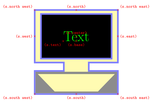
Im Grunde kann ich ja das meiste von einem Rechteck "erben" (zumindest die Anchor). Allerdings habe ich noch nie ein eigenes Shape erstellt und mit dem pgf-Layer auch nicht viel gemacht. Ich habe jetzt schon etwas rumgespielt und mich in der pgfmanual etwas eingelesen. Ein Rechteck mit den geerbten Anchors (north, south, east, west, north east, ...) habe ich hinbekommen. Der center anchor sitzt sogar fast perfekt für den Text (das grüne +). Aber ein paar fragen sind noch offen:
Ich möchte bitte vorerst keine Lösung für das Problem, da ich gerne selbst etwas rumprobieren möchte. Aber für ein paar gute Tipps wäre ich sehr dankbar. Selbstverständlich würde ich meine Lösung dann auch hier posten. |
|
Hier ist ein Vorschlag für eine solche \documentclass[margin=5mm]{standalone} \usepackage{tikz} \makeatletter \pgfdeclareshape{computer} { \savedanchor\outernortheast{% % % Calculate width and height of screen (inner rectangle) % \pgf@xa=.5\wd\pgfnodeparttextbox% \pgfmathsetlength\pgf@xc{\pgfkeysvalueof{/pgf/inner xsep}}% \advance\pgf@xa by\pgf@xc% \pgf@ya=.5\ht\pgfnodeparttextbox% \advance\pgf@ya by.5\dp\pgfnodeparttextbox% \pgfmathsetlength\pgf@yc{\pgfkeysvalueof{/pgf/inner ysep}}% \advance\pgf@ya by\pgf@yc% % % Calculate width and height of screen (outer rectangle) % \pgf@x=1.17\pgf@xa% \pgf@y=1.17\pgf@ya% % % Check against minimum height/width % \pgfmathsetlength\pgf@xb{\pgfkeysvalueof{/pgf/minimum width}}% \pgf@xb=.5\pgf@xb% \ifdim\pgf@x<\pgf@xb% % yes, too small. Enlarge... \pgf@x=\pgf@xb% \fi% \pgfmathsetlength\pgf@yb{\pgfkeysvalueof{/pgf/minimum height}}% \pgf@yb=.3125\pgf@yb% \ifdim\pgf@y<\pgf@yb% % yes, too small. Enlarge... \pgf@y=\pgf@yb% \fi% % % Add outer border % \pgfmathsetlength\pgf@xa{\pgfkeysvalueof{/pgf/outer xsep}}% \advance\pgf@x by\pgf@xa% \pgfmathsetlength\pgf@ya{\pgfkeysvalueof{/pgf/outer ysep}}% \advance\pgf@y by\pgf@ya% } \savedanchor\text{% \pgf@x=-.5\wd\pgfnodeparttextbox% \pgf@y=-.5\ht\pgfnodeparttextbox% \advance\pgf@y by.5\dp\pgfnodeparttextbox% } % % Anchors % \anchor{text}{\text}% \anchor{center}{\pgfpointorigin}% \anchor{mid}{% \pgf@process{\text}% \pgf@x=0pt% \pgfmathsetlength\pgf@ya{.5ex} \advance\pgf@y by\pgf@ya% } \anchor{base}{\pgf@process{\text}\pgf@x=0pt } \anchor{north}{\pgf@process{\outernortheast}\pgf@x=0pt} \anchor{south}{\pgf@process{\outernortheast}\pgf@x=0pt\pgf@y=-2.2\pgf@y} \anchor{west}{\pgf@process{\outernortheast}\pgf@x=-\pgf@x\pgf@y=0pt} \anchor{north west}{\pgf@process{\outernortheast}\pgf@x=-\pgf@x} \anchor{south west}{\pgf@process{\outernortheast}\pgf@x=-\pgf@x\pgf@y=-2.2\pgf@y} \anchor{east}{\pgf@process{\outernortheast}\pgf@y=0pt} \anchor{north east}{\pgf@process{\outernortheast}} \anchor{south east}{\pgf@process{\outernortheast}\pgf@y=-2.2\pgf@y} \anchorborder{% \pgf@xb=\pgf@x% xb/yb is target \pgf@yb=\pgf@y% \outernortheast% \pgf@xa=-\pgf@x% \pgf@ya=-2.2\pgf@y% \advance\pgf@x by-\pgf@xa% \advance\pgf@y by-\pgf@ya% \pgf@xc=.5\pgf@x% \pgf@yc=.5\pgf@y% \advance\pgf@xa by\pgf@xc% \advance\pgf@ya by\pgf@yc% \edef\pgf@marshal{% \noexpand\pgfpointborderrectangle {\noexpand\pgfqpoint{\the\pgf@xb}{\the\pgf@yb}} {\noexpand\pgfqpoint{\the\pgf@xc}{\the\pgf@yc}}% }% \pgf@process{\pgf@marshal}% \advance\pgf@x by\pgf@xa% \advance\pgf@y by\pgf@ya% } \backgroundpath{ %%% DRAW OUTLINE OF SHAPE %%% % store lower left in xb/yb and upper right in xa/ya \outernortheast \pgf@xa=\pgf@x \pgf@ya=\pgf@y \pgfmathsetlength\pgf@xb{-\pgf@xa} \pgfmathsetlength{\pgf@yb}{-2.2\pgf@ya} \pgfmathsetlength\pgf@xc{\pgfkeysvalueof{/pgf/outer xsep}} \pgfmathsetlength\pgf@yc{\pgfkeysvalueof{/pgf/outer ysep}} \advance \pgf@xa by -\pgf@xc \advance \pgf@ya by -\pgf@yc \advance \pgf@xb by \pgf@xc \advance \pgf@yb by \pgf@yc % move to point xa/ya (north east) \pgfpathmoveto{\pgfpoint{\pgf@xa}{\pgf@ya}} % draw a line between upper right (xa,ya) and upper left (xb,ya) \pgfpathlineto{\pgfpoint{\pgf@xb}{\pgf@ya}} \pgfpathlineto{\pgfpoint{\pgf@xb}{-\pgf@ya}} \pgfpathlineto{\pgfpoint{.3\pgf@xb}{-\pgf@ya}} \pgfpathlineto{\pgfpoint{.3\pgf@xb}{.6\pgf@yb}} \pgfpathlineto{\pgfpoint{\pgf@xb}{.6\pgf@yb}} \pgfpathlineto{\pgfpoint{\pgf@xb}{\pgf@yb}} \pgfpathlineto{\pgfpoint{\pgf@xa}{\pgf@yb}} \pgfpathlineto{\pgfpoint{\pgf@xa}{.6\pgf@yb}} \pgfpathlineto{\pgfpoint{.3\pgf@xa}{.6\pgf@yb}} \pgfpathlineto{\pgfpoint{.3\pgf@xa}{-\pgf@ya}} \pgfpathlineto{\pgfpoint{\pgf@xa}{-\pgf@ya}} \pgfpathclose } \beforebackgroundpath{ % store lower left in xb/yb and upper right in xa/ya \outernortheast \pgf@xa=\pgf@x \pgf@ya=\pgf@y \pgfmathsetlength\pgf@xb{-\pgf@xa} \pgfmathsetlength{\pgf@yb}{-2.2\pgf@ya} \pgfmathsetlength\pgf@xc{\pgfkeysvalueof{/pgf/outer xsep}} \pgfmathsetlength\pgf@yc{\pgfkeysvalueof{/pgf/outer ysep}} \advance \pgf@xa by -\pgf@xc \advance \pgf@ya by -\pgf@yc \advance \pgf@xb by \pgf@xc \advance \pgf@yb by \pgf@yc %%% DRAW SCREEN %%% \pgfsetfillcolor{black} \pgfpathmoveto{\pgfpoint{.85\pgf@xa}{.85\pgf@ya}} \pgfpathlineto{\pgfpoint{.85\pgf@xb}{.85\pgf@ya}} \pgfpathlineto{\pgfpoint{.85\pgf@xb}{-.85\pgf@ya}} \pgfpathlineto{\pgfpoint{.85\pgf@xa}{-.85\pgf@ya}} \pgfpathclose \pgfusepath{fill,stroke} %%% DRAW UPPER RECTANGLE OF CASE %%% \pgfsetfillcolor{gray!90} {\pgftransformyshift{-.5\pgflinewidth} {\pgftransformxshift{.5\pgflinewidth} \pgfpathmoveto{\pgfpoint{\pgf@xb}{.6\pgf@yb}} \pgfpathlineto{\pgfpoint{\pgf@xb}{.64\pgf@yb}} } {\pgftransformxshift{-.5\pgflinewidth} \pgfpathlineto{\pgfpoint{\pgf@xa}{.64\pgf@yb}} \pgfpathlineto{\pgfpoint{\pgf@xa}{.6\pgf@yb}} } } \pgfpathclose %%% DRAW LOWER RECTANGLE OF CASE %%% {\pgftransformyshift{.5\pgflinewidth} {\pgftransformxshift{.5\pgflinewidth} \pgfpathmoveto{\pgfpoint{\pgf@xb}{.97\pgf@yb}} \pgfpathlineto{\pgfpoint{\pgf@xb}{\pgf@yb}} } {\pgftransformxshift{-.5\pgflinewidth} \pgfpathlineto{\pgfpoint{\pgf@xa}{\pgf@yb}} \pgfpathlineto{\pgfpoint{\pgf@xa}{.97\pgf@yb}} } } \pgfpathclose %%% DRAW LEFT TRIANGLE %%% {\pgftransformxshift{.5\pgflinewidth} {\pgftransformyshift{-.5\pgflinewidth} \pgfpathmoveto{\pgfpoint{\pgf@xb}{.6\pgf@yb}} } {\pgftransformyshift{.5\pgflinewidth} \pgfpathlineto{\pgfpoint{\pgf@xb}{\pgf@yb}} \pgfpathlineto{\pgfpoint{.5\pgf@xb}{\pgf@yb}} } } \pgfpathclose %%%% DRAW RIGHT TRIANGLE %%% {\pgftransformxshift{-.5\pgflinewidth} {\pgftransformyshift{-.5\pgflinewidth} \pgfpathmoveto{\pgfpoint{\pgf@xa}{.6\pgf@yb}} } {\pgftransformyshift{.5\pgflinewidth} \pgfpathlineto{\pgfpoint{.5\pgf@xa}{\pgf@yb}} \pgfpathlineto{\pgfpoint{\pgf@xa}{\pgf@yb}} } } \pgfpathclose \pgfusepath{fill} } } \makeatother \tikzset{ shape example/.style={ text=green, draw=blue!50, fill=yellow!30, line width=.1cm, minimum size=5cm, } } \begin{document} \begin{tikzpicture} \node[shape example, computer, name=s] at (0,0) {\Huge Text}; \foreach \anchor/\placement in { north west/above left, north/above, north east/above right, west/left, center/above, east/right, text/below left,base/below, south west/below left, south/below, south east/below right% } \draw[shift=(s.\anchor),red] plot[mark=x] coordinates{(0,0)} node[\placement] {\scriptsize\texttt{(s.\anchor)}}; \end{tikzpicture} \end{document}
Vielen Dank. Ich hatte es auch schon bemerkt, allerdings keine Zeit das Problem zu lösen. Bei der Lösung ist aber auch noch einiges dabei, was ich mir nochmal genauer ansehen muss. Aber jetzt komme ich meinem Ziel schon mal einen großen Schritt näher :)
(27 Feb '14, 19:14)
funkytex
|
|
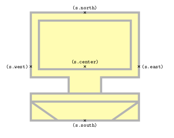
Ich habe jetzt etwas rumgespielt und habe folgendes erstellt: \documentclass{article} \usepackage{tikz} \makeatletter \pgfdeclareshape{computer}{% % inherit anchors \inheritsavedanchors[from=rectangle] \inheritanchorborder[from=rectangle] \inheritanchor[from=rectangle]{center} \inheritanchor[from=rectangle]{north} \inheritanchor[from=rectangle]{south} \inheritanchor[from=rectangle]{west} \inheritanchor[from=rectangle]{east} \backgroundpath{ %%% DRAW OUTLINE OF SHAPE %%% % store lower left in xa/ya and upper right in xb/yb \southwest \pgf@xa=\pgf@x \pgf@ya=\pgf@y \northeast \pgf@xb=\pgf@x \pgf@yb=\pgf@y % move to point xb/yb (north east) \pgfpathmoveto{\pgfpoint{\pgf@xb}{\pgf@yb}} % draw a line between upper right (xb,yb) and upper left (xa,yb) \pgfpathlineto{\pgfpoint{\pgf@xa}{\pgf@yb}} \pgfpathlineto{\pgfpoint{\pgf@xa}{.2\pgf@ya}} \pgfpathlineto{\pgfpoint{.3\pgf@xa}{.2\pgf@ya}} \pgfpathlineto{\pgfpoint{.3\pgf@xa}{.5\pgf@ya}} \pgfpathlineto{\pgfpoint{\pgf@xa}{.5\pgf@ya}} \pgfpathlineto{\pgfpoint{\pgf@xa}{\pgf@ya}} \pgfpathlineto{\pgfpoint{\pgf@xb}{\pgf@ya}} \pgfpathlineto{\pgfpoint{\pgf@xb}{.5\pgf@ya}} \pgfpathlineto{\pgfpoint{.3\pgf@xb}{.5\pgf@ya}} \pgfpathlineto{\pgfpoint{.3\pgf@xb}{.2\pgf@ya}} \pgfpathlineto{\pgfpoint{\pgf@xb}{.2\pgf@ya}} \pgfpathclose %%% DRAW SCREEN %%% \color{black} \pgfpathmoveto{\pgfpoint{.85\pgf@xb}{.85\pgf@yb}} \pgfpathlineto{\pgfpoint{.85\pgf@xa}{.85\pgf@yb}} \pgfpathlineto{\pgfpoint{.85\pgf@xa}{.05\pgf@ya}} \pgfpathlineto{\pgfpoint{.85\pgf@xb}{.05\pgf@ya}} \pgfpathclose %%% DRAW UPPER RECTANGLE OF CASE %%% \pgfpathmoveto{\pgfpoint{\pgf@xa}{.5\pgf@ya}} \pgfpathlineto{\pgfpoint{\pgf@xa}{.65\pgf@ya}} \pgfpathlineto{\pgfpoint{\pgf@xb}{.65\pgf@ya}} \pgfpathlineto{\pgfpoint{\pgf@xb}{.5\pgf@ya}} \pgfpathclose %%% DRAW LEFT TRIANGLE %%% \color{gray} \pgfpathmoveto{\pgfpoint{\pgf@xa}{.65\pgf@ya}} \pgfpathlineto{\pgfpoint{\pgf@xa}{\pgf@ya}} \pgfpathlineto{\pgfpoint{.5\pgf@xa}{\pgf@ya}} \pgfpathclose %%% DRAW RIGHT TRIANGLE %%% \color{gray} \pgfpathmoveto{\pgfpoint{\pgf@xb}{.65\pgf@ya}} \pgfpathlineto{\pgfpoint{.5\pgf@xb}{\pgf@ya}} \pgfpathlineto{\pgfpoint{\pgf@xb}{\pgf@ya}} \pgfpathclose } } \makeatother \tikzset{ shape example/.style={ color=black!30, draw, fill=yellow!30, line width=.1cm, inner xsep=2.5cm, inner ysep=2.5cm } } \begin{document} \begin{tikzpicture} \node[shape example, computer, name=s] at (0,0) {}; \foreach \anchor/\placement in {north/above, west/left, center/above, east/right, south/below} \draw[shift=(s.\anchor)] plot[mark=x] coordinates{(0,0)} node[\placement] {\scriptsize\texttt{(s.\anchor)}}; \end{tikzpicture} \end{document} Das Ergebnis sieht wie folgt aus:
Die
(27 Feb '14, 15:57)
esdd
|
|
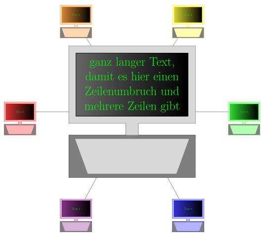
Da pgf / TikZ 3.0 jetzt auf CTAN und auch bei TeXlive 2013 ist, kann man statt einer
\documentclass[tikz,margin=5mm]{standalone} \usetikzlibrary{fit} \usepackage[ngerman]{babel} \tikzset{ comp/.style={ thick, minimum width=8cm,minimum height=4.5cm,text width=8cm,inner sep=0pt, text=green,align=center,font=\Huge, transform shape }, monitor/.style={draw=none,xscale=18/16,yscale=11/9}, display/.style={shading=axis,left color=black!60, right color=black}, ut/.style={fill=gray} } \tikzset{ computer/.pic={ % Monitor (mit Rand) \node(-m)[comp,pic actions,monitor]{\phantom{\parbox{\linewidth}{\tikzpictext}}}; % Display (ohne Rand) \node[comp,pic actions,display]{\tikzpictext}; \begin{scope}[x=(-m.east),y=(-m.north)] % Füllen des Unterteils \path[pic actions,draw=none] ([yshift=2\pgflinewidth]-0.1,-1)--(-0.1,-1.3)--(-1,-1.3)-- (-1,-2.4)--(1,-2.4)--(1,-1.3)--(0.1,-1.3)--([yshift=2\pgflinewidth]0.1,-1); % Färben des Randes des Unterteils \path[ut] (-1,-2.4)rectangle(1,-1.3) (-0.9,-1.4)--(-0.7,-2.3)--(0.7,-2.3)--(0.9,-1.4)--cycle; % Zeichnen der Umrandung des gesamten Computers \path[pic actions,fill=none] (-1,1)--(-1,-1)--(-0.1,-1)--(-0.1,-1.3)--(-1,-1.3)-- (-1,-2.4)coordinate(sw)coordinate[pos=0.5](-b west)-- (1,-2.4)--(1,-1.3)coordinate[pos=0.5](-b east)-- (0.1,-1.3)--(0.1,-1)--(1,-1)--(1,1)--cycle; % Node um gesamten Computer \node(-c)[fit=(sw)(-m.north east),inner sep=0pt]{}; \end{scope} } } % Es stehen zwei rechteckige Noden mit den üblichen Ankern zur Verfügung: % Monitor (mit Rand): <picname>-m, gesamter Computer: <picname>-c % Der Anker des gesamten pics ist bei <picname>-m.center (nicht änderbar) \begin{document} \begin{tikzpicture} \pic(comp0)[ draw, fill=gray!30, pic text={ganz langer Text, damit es hier einen Zeilenumbruch und mehrere Zeilen gibt} ] {computer}; \path(comp0-c.center) pic foreach[count=\i] \farbe in {yellow,orange,red, red!50!blue, blue,green}(comp\i) [ draw=\farbe, fill=\farbe!30, display/.append style={left color=\farbe!80!black!80}, scale=0.25, pic text={Text \i} ] at +(60*\i:8){computer}; \foreach \i in {1,2,4,5}\draw (comp\i-c)--(comp0-c); \foreach \i in {3,6}\draw (comp\i-m)--(comp0-c); \end{tikzpicture} \end{document} |


Sehr interessant! Wenn Du uns was zum Bearbeiten gibst, hätten wir was zum Basteln... Du könntest ja Deinen Entwurf hier posten, direkt in die Frage hinein editiert (nicht als Antwort - über "Bearbeiten" die Frage aktualisieren).
@funkytex Tipps, wie TeXwelt funktioniert: Fragen nach allgemeinen Tipps sind ok, die spezifischen unterschiedlichen (Teil-)Probleme wären jedoch optimal in eigenen Fragen aufgehoben. Wir sortieren thematisch fürs Lösungsarchiv, und so werden Ergebnisse klarer und öfter nutzbar, auf unterschiedliche Anwendungsfälle. Also etwa als neue Frage(n): "Wie kann ich einem Shape einen Schatten hinzufügen?", "Wie kann ich eine Füllfarbe unveränderlich fest einstellen?", ... je mehr konkrete Fragen, desto besser. Sammelfragen sind kaum sortierbar und der Blick auf die Einzellösungen ist schwerer.
Was möglich wäre: Eine der zahlreichen Vektorgraphiken (vgl. https://duckduckgo.com/?q=vector+graphics+computer) in Inkscape laden und dort in TikZ-Code umwandeln. Allerdings ist der dann üblicherweise alles andere als optimierter Code.
Bitte entschuldigt, ich habe die Kommentare erst jetzt gesehen. Inzwischen habe ich eine Idee, wie ich es lösen könnte. Ich versuche morgen nachmittag weiter daran zu arbeiten, aber ich werde euch selbstverständlich auf dem laufenden halten.