|
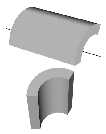
Moin Zusammen, ich brauche einen Zylinder wie das Beispiel aber statt eine komplette Runde in Umfangsrichtung würde 1/3 Kreis haben (120 Grad). Kann jemand mir dabei helfen? Vielen Dank im Voraus. Grüße \documentclass{article} \usepackage{tikz} \usetikzlibrary{shapes.geometric,calc} \begin{document} \begin{tikzpicture} \begin{scope}[rotate=15] \node[transform shape,ellipse,minimum height=2cm,minimum width=1cm,draw,outer sep=0] (a) {}; \clip[scale=0.8,postaction={line width=0.8pt,draw}] (a) circle (0.5 and 1); \draw[scale=0.8] ([shift={($0.75*({cos(15)},{sin(15)})$)}]a) circle (0.5 and 1); \draw(a.west) -- (a.east); \end{scope} \begin{scope}[rotate=15] \draw (a.north) -- ++(0.75,0) arc (90:-90:0.5cm and 1cm-2\pgflinewidth) -- (a.south); \draw (a.east) ++(0.75,0) -- ++(1cm,0) (a.west) ++(-0.75,0) -- ++(0.9cm,0); \end{scope} \end{tikzpicture} \end{document} |
|
Das folgende Beispiel musst du mit \documentclass{article} \usepackage{pst-solides3d} \begin{document} \psset{unit=0.6} \psset{lightsrc=viewpoint,viewpoint=50 35 25 rtp2xyz,Decran=50} \begin{pspicture}(-6,-3)(5,4) \psSolid[object=line,args=0 -7 0 0 5 0] \defFunction{F}(t){t cos 3 mul}{t sin 3 mul}{} \defFunction{G}(t){t cos 2 mul}{t sin 2 mul}{} \psSolid[object=prisme,h=8,fillcolor=black!30, RotX=90,base=0 120 {F} CourbeR2+ 120 0 {G} CourbeR2+,grid](0,4,0) %\axesIIID(3,4,3)(8,6,7) \end{pspicture} \psset{lightsrc=viewpoint,viewpoint=50 90 -25 rtp2xyz,Decran=50} \begin{pspicture}(-6,-3)(5,4) \defFunction{F}(t){t cos 3 mul}{t sin 3 mul}{} \defFunction{G}(t){t cos 2 mul}{t sin 2 mul}{} \psSolid[object=prisme,h=8,fillcolor=black!30, RotX=90,base=0 120 {F} CourbeR2+ 120 0 {G} CourbeR2+,grid](0,4,0) %\psSolid[object=line,args=0 -7 0 0 7 0] %\axesIIID(3,4,3)(8,6,7) \end{pspicture} \end{document}
Interessante Alternative. Kannst du noch etwas schreiben, was
(17 Aug '16, 21:17)
sudo
@sudo Ich vermute, das war bewusst eine kurze Demo, und man könnte sich über texdoc.net/pkg/pst-solides3d informieren... andernfalls müsste man sehr tief Luft holen :-) in Kürze: richtige 3D-Projektion mit einer Menge vordefinierter parametrisierter Körper mit Lichtquelle, das gibt es halt in TikZ nicht bzw. man behilft sich mit Eigenkonstruktion und Shading o.a. Es basiert auf PSTricks.
(17 Aug '16, 22:44)
stefan ♦♦
@stefan danke dir erstmal und zweitens kriege ich "undefined control sequence" Error beim kompilieren (mit xelatex) bei Definition der Funktionen. Soll ich die Usepackage per hand installieren?
(18 Aug '16, 09:32)
vague_creature
@vague_creature Dieser Fehler kommt mit
(18 Aug '16, 11:26)
stefan ♦♦
@vague_creature: Welchen Editor verwendest du? Dann kann man dir genau sagen, wo man das
einstellt, dass
(18 Aug '16, 18:47)
crazyhorse
@sudo: wenn du es vergleichen willst, dann nur
(18 Aug '16, 19:35)
crazyhorse
Mir ging es nicht unbedingt um einen Vergleich und es sollte auch kein langer Text werden. Die Schlagwörter Verdeckte Linien und Körper mit Lichtquelle sind auf jeden Fall schon gut. PS: Für manchen Googler ist ein Link zu CTAN ganz nett.
(18 Aug '16, 21:44)
sudo
Ergebnis 5 von 7
show 2 more comments
|
|
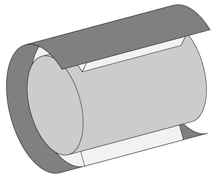
Ich habe mal etwas ähnliches gemacht. Vielleicht kannst du davon etwas ableiten: \documentclass[tikz, margin=1mm]{standalone} \newcommand{\LongHalfLarge}{2.6} \newcommand{\ShortHalfLarge}{1.3} \newcommand{\LongAndShortHalfLarge}{2.6 and 1.3} \newcommand{\LongHalfSmall}{2} \newcommand{\ShortHalfSmall}{1} \newcommand{\LongAndShortHalfSmall}{2 and 1} \begin{document} \tikzset{mono/.style={fill=gray!40}, mat/.style={fill=gray!10}, sleeve/.style={fill=gray}} %\tikzset{debug/.style={draw=magenta, very thick}} % For debugging only \tikzset{debug/.style={}} % For final version \begin{tikzpicture}[rotate=105] %% Blech hinten \coordinate (blech oben) at (0,0); \coordinate (blech unten) at (0,-6); \coordinate (mono oben) at (0,-.5); \coordinate (mono unten) at (0,-5.5); \coordinate (matte oben) at (0,-1); \coordinate (matte unten) at (0,-5); %% Blech hinten \draw[sleeve] (blech unten) ++ (0:\LongHalfLarge) arc (0:180:\LongAndShortHalfLarge) -- ({blech oben} -| {(-\LongHalfLarge,1)}) arc (180:0:\LongAndShortHalfLarge) -- cycle; %% Matte hinten \draw[mat] (matte unten) ++ (0:\LongHalfLarge) arc (0:180:\LongAndShortHalfLarge) -- ({matte oben} -| {(-\LongHalfLarge,1)}) arc (180:0:\LongAndShortHalfLarge) -- cycle; \draw[mat] (matte oben) ++ (180:\LongHalfSmall) -- ++ (180:\LongHalfLarge - \LongHalfSmall) -- ({matte unten} -| {(-\LongHalfLarge,0)}) -- ++ (0:\LongHalfLarge - \LongHalfSmall) -- cycle; %% Mono \draw[mono] (mono unten) ++ (0:\LongHalfSmall) arc (360:180:\LongAndShortHalfSmall) -- ({mono oben} -| {(-\LongHalfSmall,1)}) arc (180:0:\LongAndShortHalfSmall) -- cycle; \draw[mono] (mono oben) ++ (0:\LongHalfSmall) arc (0:360:\LongAndShortHalfSmall) -- cycle; %% Matte vorne rechts \path [debug] (matte oben) ++ (0:\LongHalfLarge) arc (0:-60:\LongAndShortHalfLarge) coordinate (mat 0); \draw [mat] (matte oben) ++ (0:\LongHalfSmall) arc (0:-60:\LongAndShortHalfSmall) coordinate (mat 1) -- (mat 0) arc(-60:0:\LongAndShortHalfLarge); \path [debug] (matte unten) ++ (0:\LongHalfLarge) arc (0:-60:\LongAndShortHalfLarge) coordinate (mat 3); \draw [mat] (matte unten) ++ (0:\LongHalfSmall) arc (0:-60:\LongAndShortHalfSmall) coordinate (mat 2) -- (mat 3) arc(-60:0:\LongAndShortHalfLarge); \draw[mat] (mat 0) -- (mat 1) -- (mat 2) -- (mat 3) -- cycle; %% Blech vorne rechts \path [debug] (blech oben) ++ (0:\LongHalfLarge) arc (0:-60:\LongAndShortHalfLarge) coordinate (blech 0); \draw [sleeve] (blech unten) ++ (0:\LongHalfLarge) arc (0:-60:\LongAndShortHalfLarge) -- (blech 0) arc (-60:0:\LongAndShortHalfLarge) -- cycle; %% For Debugging only \path [debug] (matte unten) circle (3pt); \path [debug] (matte oben) circle (3pt); \path [debug] (blech unten) circle (3pt); \path [debug] (blech oben) circle (3pt); \path [debug] (mono unten) circle (3pt); \path [debug] (mono oben) circle (3pt); \end{tikzpicture} \end{document} Ich habe dafür einfach die Teile zerlegt und von hinten nach vorne gezeichnet.
|


An und für sich, ist das mit den
arc(<Start-Winkel>:<End-Winkel>:<Erste Halbachse> and <Zweite Halbachse>)-Befehlen kein Problem. Kannst du ein Bild einfügen, welches das Ergebnis skizziert oder beschreiben, von wo nach wo der Kreis geöffnet werden soll?Hi, es ist mir eigentlich egal, wo die Kurve anfängt oder endet kann ich später alles anpassen...haupsache möchte ich eine 120 grad Segment haben