|
Sehr oft wird bei Tikz-Bildern ein Kann jemand einfach erklären, wie der Gedankengang ist, wenn man z.B. |
|
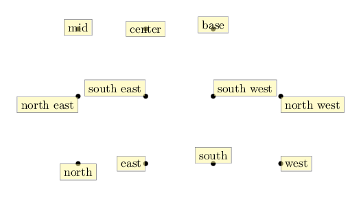
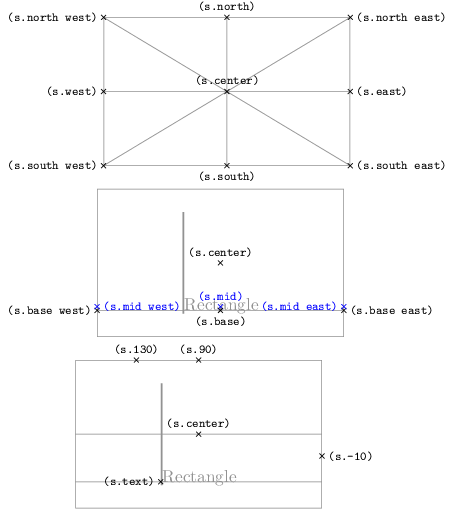
Die Standard-Anker kann man sich mit folgendem Schaubild klarmachen: \documentclass[border=5mm]{standalone} \usepackage{tikz} \begin{document} \begin{tikzpicture}[x=2cm, y=2cm, every node/.style={draw, fill=yellow!50, opacity=0.5, text opacity=1} ] \draw [help lines, step=2cm] (0,0) grid (3,2); \fill (0,0) circle (2pt) node[anchor=north]{north}; \fill (1,0) circle (2pt) node[anchor=east]{east}; \fill (2,0) circle (2pt) node[anchor=south]{south}; \fill (3,0) circle (2pt) node[anchor=west]{west}; \fill (0,1) circle (2pt) node[anchor=north east]{north east}; \fill (1,1) circle (2pt) node[anchor=south east]{south east}; \fill (2,1) circle (2pt) node[anchor=south west]{south west}; \fill (3,1) circle (2pt) node[anchor=north west]{north west}; \fill (0,2) circle (2pt) node[anchor=mid]{mid}; \fill (1,2) circle (2pt) node[anchor=center]{center}; \fill (2,2) circle (2pt) node[anchor=base]{base}; \end{tikzpicture} \end{document} Daneben gibt es weitere Anker. Gleichwohl lassen sich mit Ankern spezifische Koordinaten ansteuern; hier am Beispiel eines %\documentclass[]{article} \documentclass[border=5mm, varwidth]{standalone} \usepackage{tikz} \begin{document} \begin{tikzpicture}[ every node/.style={font=\ttfamily\scriptsize}, mystyle/.style={gray, thin}, ] \node[name=s,gray, rectangle, draw,mystyle, minimum width=5cm, minimum height=3cm] {}; \draw[mystyle] (s.north) -- (s.south); \draw[mystyle] (s.east) -- (s.west); \draw[mystyle] (s.north east) -- (s.south west); \draw[mystyle] (s.south east) -- (s.north west); \draw[] plot[mark=x] coordinates{(s.center)} node[above]{(s.center)}; \draw[] plot[mark=x] coordinates{(s.north)} node[above]{(s.north)}; \draw[] plot[mark=x] coordinates{(s.east)} node[right]{(s.east)}; \draw[] plot[mark=x] coordinates{(s.south)} node[below]{(s.south)}; \draw[] plot[mark=x] coordinates{(s.west)} node[left]{(s.west)}; \draw[] plot[mark=x] coordinates{(s.north east)} node[right]{(s.north east)}; \draw[] plot[mark=x] coordinates{(s.south east)} node[right]{(s.south east)}; \draw[] plot[mark=x] coordinates{(s.south west)} node[left]{(s.south west)}; \draw[] plot[mark=x] coordinates{(s.north west)} node[left]{(s.north west)}; \end{tikzpicture} \begin{tikzpicture}[ every node/.style={font=\ttfamily\scriptsize}, mystyle/.style={gray, thin}, ] \node[name=s,gray, rectangle, draw,mystyle, minimum width=5cm, minimum height=3cm, text=gray, font=\normalsize] {\vrule width 1pt height 2cmRectangle}; \draw[mystyle] (s.base west) -- (s.base east); \draw[] plot[mark=x] coordinates{(s.center)} node[above]{(s.center)}; \draw[blue] plot[mark=x] coordinates{(s.mid)} node[above]{(s.mid)}; \draw[] plot[mark=x] coordinates{(s.base)} node[below]{(s.base)}; \draw[] plot[mark=x] coordinates{(s.base west)} node[left]{(s.base west)}; \draw[] plot[mark=x] coordinates{(s.base east)} node[right]{(s.base east)}; \draw[blue] plot[mark=x] coordinates{(s.mid west)} node[right]{(s.mid west)}; \draw[blue] plot[mark=x] coordinates{(s.mid east)} node[left]{(s.mid east)}; \end{tikzpicture} \centering\begin{tikzpicture}[ every node/.style={font=\ttfamily\scriptsize}, mystyle/.style={gray, thin}, ] \node[name=s,gray, rectangle, draw,mystyle, minimum width=5cm, minimum height=3cm, text=gray, font=\normalsize] {\vrule width 1pt height 2cmRectangle}; \draw[mystyle] (s.west) -- (s.east); \draw[mystyle] (s.base west) -- (s.base east); \draw[] plot[mark=x] coordinates{(s.center)} node[above]{(s.center)}; \draw[] plot[mark=x] coordinates{(s.text)} node[left]{(s.text)}; \draw[] plot[mark=x] coordinates{(s.-10)} node[right]{(s.-10)}; \draw[] plot[mark=x] coordinates{(s.90)} node[above]{(s.90)}; \draw[] plot[mark=x] coordinates{(s.130)} node[above]{(s.130)}; \end{tikzpicture} \end{document} @cis Sehr schön! Das hilft nun jedem, der nach TikZ anchor setzen googelt, und im dicken Handbuch nicht gefunden hat. In diesem Sinne sind für mich auch einfache Fragen willkommen, erst recht wenn man sie sogar selber beantwortet. Mehr Sachen zu finden bedeutet mehr Gäste auf TeXwelt und vielleicht dann neue Mitbewohner. ;-)
(08 Feb '18, 15:21)
stefan ♦♦
Alles klar ;)
(08 Feb '18, 15:25)
cis
|


Hast Du schon das Kapitel 17.5.1 Positioning Nodes Using Anchors auf Seite 227 im aktuellen pgfmanual gelesen? Da steht das wesentliche nämlich drin.
Jetzt schon. Ziemlich knapp gehalten, dafür dass das so oft vorkommt. :)
Im Teil IV Abschnitt 5 (Anchoring) des
chemfig-Handbuchs gibt es auch ein schönes Bild mit einer Übersicht der verfügbaren Anker.Ja, das findet man so ähnlich im Tikz-Handbuch. Ich wollte ggf. noch sowas ergänzen, möglichst etwas ausführlicher. Ich bin noch nicht dazu gekommen.