|
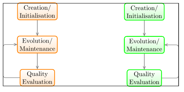
Das entscheidene Wort meiner Frage ist exakt. Ich definiere einen Scope und setze eine lokale Bounding Box, aus der also ein Node erzeugt wird. Nun möchte ich einen zweiten Scope spezifizieren, der 4cm rechts neben dem zuvor definierten Scope positioniert werden soll. Das Problem, was ich habe, ist, dass der zweite Scope nicht ganz exakt positioniert wird. Zur Veranschaulkichung habe ich ein Beispiel angefügt, wo ich die Bounding Box beider Scopes mit einzeichne. Zu erkennen ist dort, dass die orange Linie des linken Scopes einen Tick über der Bounding Box beginnt und die grüne Linie des rechten Scopes einen Tick unter der Bounding Box endet. Was ich möchte ist, dass beide exakt auf der selben Höhe beginnen (und in diesem Fall dann auch auf der gleichen Höhe enden würden). Wie erreiche ich das? \documentclass{scrartcl} \usepackage{tikz} \usetikzlibrary{calc} \begin{document} \tikzset{ state/.style = { rectangle, minimum size=6mm, very thick, draw=#1, rounded corners=4pt, top color=white, bottom color=#1!20, align=center, }, model 1/.style = {state = orange}, model 2/.style = {state = green}, skip vert/.style = {to path={-- ++(0,#1) -| (\tikztotarget)}}, skip hori/.style = {to path={-- ++(#1,0) |- (\tikztotarget)}}, } \begin{tikzpicture}[ node distance=2.0cm, thick, every edge/.style={ rounded corners ,draw=black!50 ,text=black,font=\sffamily\scriptsize,near end, thick, ->, },] % left model \begin{scope}[local bounding box=scope left] \node[model 1] (init m1) {Creation/\\ Initialisation}; \node[model 1] (evo m1) [below of = init m1] {Evolution/\\ Maintenance}; \node[model 1] (qual m1) [below of = evo m1] {Quality\\ Evaluation}; \path (init m1) edge (evo m1) (evo m1) edge (qual m1) (qual m1.west) edge[skip hori=-10mm] (evo m1.west) ; \end{scope} %\draw (scope left.south west) rectangle (scope left.north east); % right model \begin{scope}[shift={($(scope left.north east)+(4cm, 0)$)}, anchor=north west ,local bounding box=scope right] \node[model 2] (init m1) {Creation/\\ Initialisation}; \node[model 2] (evo m1) [below of = init m1] {Evolution/\\ Maintenance}; \node[model 2] (qual m1) [below of = evo m1] {Quality\\ Evaluation}; \path (init m1) edge (evo m1) (evo m1) edge (qual m1) (qual m1.east) edge[skip hori=10mm] (evo m1.east) ; \end{scope} \draw (scope left.south west) rectangle (scope right.north east); \end{tikzpicture} \end{document} Hier noch ein Screenshot, der das Ergebnis zeigt.
|
|
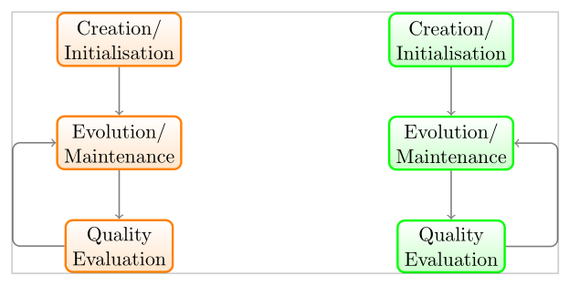
Mit \begin{scope}[shift={($(scope left.north east)+(4cm, 0)$)}, anchor=north west ,local bounding box=scope right] richtest Du nicht den \begin{scope}[shift={($(scope left.north east)+(4cm, 0)$)}, anchor=north west ,local bounding box=scope right] \node[model 2,anchor=south] (init m1) {Creation/\\ Initialisation}; \node[model 2] (evo m1) [below of = init m1] {Evolution/\\ Maintenance}; \node[model 2] (qual m1) [below of = evo m1] {Quality\\ Evaluation}; \path (init m1) edge (evo m1) (evo m1) edge (qual m1) (qual m1.east) edge[skip hori=10mm] (evo m1.east) ; \end{scope} liefert Prinzipiell wäre es einfacher, wenn Du die Positionierung ohne die \begin{scope}[shift={($(scope left.north east)+(4cm,\pgfkeysvalueof{/pgf/outer ysep})$)} ,anchor=north west,local bounding box=scope right]
Zum Zeichnen des Rahmens habe ich den Node Code: \documentclass{scrartcl} \usepackage{tikz} \usetikzlibrary{calc} \begin{document} \tikzset{ state/.style = { rectangle, minimum size=6mm, very thick, draw=#1, rounded corners=4pt, top color=white, bottom color=#1!20, align=center, }, model 1/.style = {state = orange}, model 2/.style = {state = green}, skip vert/.style = {to path={-- ++(0,#1) -| (\tikztotarget)}}, skip hori/.style = {to path={-- ++(#1,0) |- (\tikztotarget)}}, } \begin{tikzpicture}[, node distance=2.0cm, thick, every edge/.style={ rounded corners ,draw=black!50 ,text=black,font=\sffamily\scriptsize,near end, thick, ->, },] % left model \begin{scope}[local bounding box=scope left] \node[model 1] (init m1) {Creation/\\ Initialisation}; \node[model 1] (evo m1) [below of = init m1] {Evolution/\\ Maintenance}; \node[model 1] (qual m1) [below of = evo m1] {Quality\\ Evaluation}; \path (init m1) edge (evo m1) (evo m1) edge (qual m1) (qual m1.west) edge[skip hori=-10mm] (evo m1.west) ; \end{scope} % right model \begin{scope}[shift={($(scope left.north east)+(4cm,\pgfkeysvalueof{/pgf/outer ysep})$)} ,anchor=north west,local bounding box=scope right] \node[model 2] (init m1) {Creation/\\ Initialisation}; \node[model 2] (evo m1) [below of = init m1] {Evolution/\\ Maintenance}; \node[model 2] (qual m1) [below of = evo m1] {Quality\\ Evaluation}; \path (init m1) edge (evo m1) (evo m1) edge (qual m1) (qual m1.east) edge[skip hori=10mm] (evo m1.east) ; \end{scope} \draw[opacity=.2] (current bounding box.south west) rectangle (current bounding box.north east); \end{tikzpicture} \end{document} |


