|
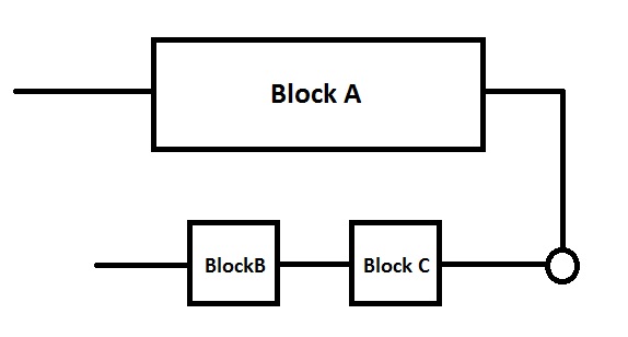
Hallo, Ich versuche gerade mit Tikz eine Zustandsregelung zu zeichnen. Das Beispiel auf Texample geht schonmal in die Richtung. Es gibt jedoch ein Problem. Hier meine Frage: Wie kann man unter den Block rechts oben, anstatt nur einen Block (ei = (yi - y~i)) darunter zu setzen, zwei Blöcke darunter setzen. Prinzipskizze:
Vielen Dank schonmal |
|
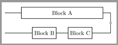
Die Syntax des verlinkten Beispiels ist nicht mehr ganz aktuell: verwende Wenn die \documentclass[margin=5pt]{standalone} \usepackage{tikz} \usetikzlibrary{matrix} \tikzset{ block/.style = {draw,rectangle,thick,minimum size=2em}, branch/.style = {circle,inner sep=0pt,minimum size=1mm,draw=black}, line/.style = {thick}, } \begin{document} \begin{tikzpicture} \matrix [ ampersand replacement=\&, row sep=0.2cm, column sep=0.4cm, matrix of nodes, nodes={anchor=center} ] { % |[block,minimum width=5cm](A)|Block A \\ \&|[branch](u)| \\ \node[block,anchor=east,xshift=-1em] (B){Block B}; \node[block,anchor=west,xshift=1em] (C){Block C};\\ }; \draw[line] (A.west)+(-1,0)coordinate(h)--(A)-|(u)|-(C)--(B)--(B-|h); \end{tikzpicture} \end{document} Ergebnis:
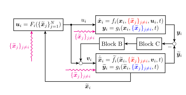
In dem von Dir verlinkten Beispiel bietet sich die Option % ursprüngliche Quelle: http://www.texample.net/tikz/examples/observer-estimator/ % Author: Dominik Haumann % Änderungen: esdd \documentclass[landscape,a5paper,11pt]{article} \usepackage[utf8]{inputenc} % utf8 encoding \usepackage[T1]{fontenc} % use T1 fonts \usepackage{amsmath} % nice math symbols \usepackage{bm} % bold math \usepackage{tikz} \usetikzlibrary{decorations.pathmorphing} % for snake lines \usetikzlibrary{matrix} % for block alignment \usetikzlibrary{arrows} % for arrow heads \usetikzlibrary{calc} % for manimulation of coordinates % TikZ styles for drawing \tikzset{ block/.style = {draw,rectangle,thick,minimum size=2em}, sum/.style = {draw,circle,inner sep=0mm,minimum size=2mm}, line/.style = {thick}, connector/.style = {->,line}, branch/.style = {circle,inner sep=0pt,minimum size=1mm,fill=black,draw=black}, guide/.style = {}, snakeline/.style = { connector, decorate, decoration={pre length=0.2cm, post length=0.2cm, snake, amplitude=.4mm, segment length=2mm},thick, magenta, ->} } \renewcommand{\vec}[1]{\ensuremath{\boldsymbol{#1}}} % bold vectors \def \myneq {\skew{-2}\not =} % \neq alone skews the dash \begin{document} \begin{tikzpicture}[auto, >=stealth'] \small % node placement with matrix library: 5x4 array \matrix[ ampersand replacement=\&, row sep=0.2cm, column sep=0.4cm, matrix of math nodes, nodes={anchor=center} ] { % |[block] (F1)| \vec{u}_i = F_i(\{\widetilde{\vec{x}}_j\}_{j=1}^N) \& |[branch] (u1)| \& \&[1em]% <- etwas mehr Abstand, damit Platz für die Beschriftung ist |[block] (f1)| \begin{matrix} \dot{\vec{x}}_i = f_i(\vec{x}_i, \textcolor{red}{\{\widetilde{\vec{x}}_j\}_{j \myneq i}}, \vec{u}_i, t)\\ \vec{y}_i = g_i(\vec{x}_i, \textcolor{blue}{\{\widetilde{\vec{x}}_j\}_{j \myneq i}}, t) \end{matrix} \& \\ \& \& \& \node[block,anchor=east,xshift=-1em] (L1a){\text{Block B}}; \node[block,anchor=west,xshift=1em] (L1b){\text{Block C}}; \& |[sum] (e1)| \\ \& \& |[sum] (v1)| \& |[block] (o1)| \begin{matrix} \dot{\widetilde{\vec{x}}}_i = \widetilde{f}_i(\widetilde{\vec{x}}_i, \textcolor{red}{\{\widetilde{\vec{x}}_j\}_{j \myneq i}}, \vec{v}_i, t)\\ \widetilde{\vec{y}}_i = g_i(\widetilde{\vec{x}}_i, \textcolor{blue}{\{\widetilde{\vec{x}}_j\}_{j \myneq i}}, t) \end{matrix} \& \\ |[guide] (i1)| \& \& \& \& \\ }; % now link the nodes \draw [line] (F1) -- (u1); \draw [connector] (u1) -- node {$u_i$} (f1); \draw [connector] (f1) -| node[near end] {$\vec{y}_i$} (e1); \draw [connector] (e1) -- (L1b); \draw [connector] (L1b) -- (L1a); \draw [connector] (L1a) -| (v1); \draw [connector] (v1) -- node {$\vec{v}_i$} (o1); \draw [connector] (u1) |- (v1); \draw [connector] (o1) -| node[pos=0.96] {$-$} node [near end, swap] {$\widetilde{\vec{y}}_i$} (e1); \draw [connector] (o1.south) -- ++(0,-.5cm) -| node [near start] {$\widetilde{\vec{x}}_i$} ($(F1.south) + (0.4cm, 0em)$); % draw the snake lines with offset (using the calc library) \draw [snakeline] ($(i1) - (0.4cm, -1cm)$) -- node {$\{\widetilde{\vec{x}}_j\}_{j \myneq i}$} ($(F1.south) - (0.4cm, 0em)$); \draw [snakeline, swap] ($(v1.east) - (1.0cm, 0.4cm)$) -- node {$\{\widetilde{\vec{x}}_j\}_{j \myneq i}$} ($(o1.west) - (0cm, 0.4cm)$); \draw [snakeline, swap] ($(u1.east) + (0.1cm, -0.4cm)$) -- node {$\{\widetilde{\vec{x}}_j\}_{j \myneq i}$} ($(f1.west) - (0cm, 0.4cm)$); \end{tikzpicture} \end{document} Ergebnis:
|


