|
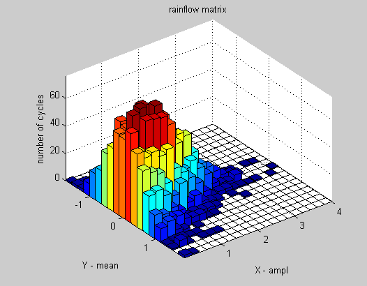
Wie komme ich zu folgender Darstellung meines Diagrammes? Danke für eure Hilfe.
Quellcode: \documentclass{article} \usepackage{tikz,pgfplots} \begin{document} \pgfplotsset{width=15cm,height=10cm} \begin{tikzpicture} \begin{axis}[colorbar sampled, colorbar style={samples=13}, grid=both, scale only axis=true, width=10cm, height=15cm, xtick={0,1,...,10}, ytick={-8,-7,...,10}, xmin=0, xmax=10, ymin=-8, ymax=8, ] \addplot3[ scatter,mark=text, text mark={\rule{6mm}{3mm}},only marks, point meta=\thisrow{myvalue} ] table { x y color myvalue 2 3 1 100 4 3 2 3 2 7 3 0.75 7 7 4 45 8 5 2 3 2 5 1 10 4 -4 2 1 4 1 3 75 5 -1 4 4 5 2 2 3 1 -2 1 10 2 5 2 5 3 -8 3 75 4 5 4 42 7 -2 2 2 }; \end{axis} \end{tikzpicture} \end{document} |
|
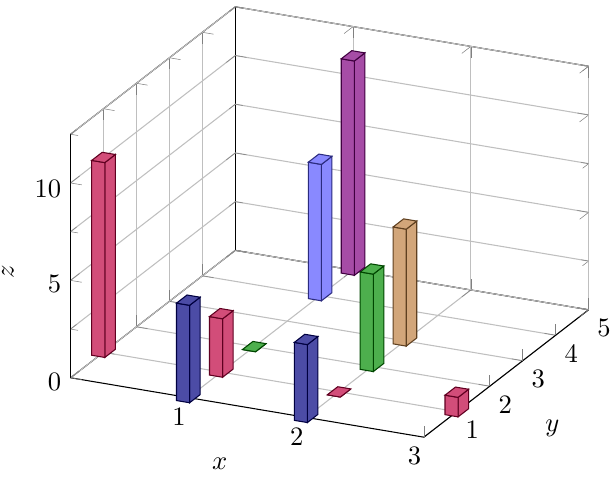
Ungeachtet des Umstandes, dass das eine perspektivisch verwirrende Darstellung ist, kann man mit pgfplots ein 3D-Bardiagramm so erstellen: Die Idee ist Setzt man z.B. Die richtige Höhe der cubes kann mit €dit: Es zeigt sich, dass es sinnvoll ist \documentclass[border=5pt, tikz]{standalone} \usepackage{pgfplots} \usepackage{pgfplotstable} \pgfplotsset{compat=1.17} \usetikzlibrary{calc} \def\pgfmathsetglobalmacro#1#2{\pgfmathparse{#2}% \global\let#1\pgfmathresult} \pgfplotsset{ colormap = {mycolormap}{ color(0) = (blue!50!black); color(1) = (purple); color(2) = (green!55!black); color(3) = (brown); color(4) = (blue!66) color(5) = (violet) }, colormap name=mycolormap, %colormap name=viridis } \begin{document} \pgfplotstableread[col sep=comma,header=true]{ X, Y, Z 2, 0, 4 1, 0, 5 0, 1, 10 3, 1, 1 1, 1, 3 2, 1, 0 1, 2, 0 2, 2, 5 2, 3, 6 1, 4, 7 1, 5, 11 }{\datatable} \begin{tikzpicture}[] \begin{axis}[ %height=2cm, width=7cm, % view={120}{40}, x dir=reverse, xmin=0, ymin=0, zmin=0, enlarge z limits={rel=0.25,upper}, xtick={1,...,10}, ytick={1,...,10}, grid=both, xlabel={$x$}, ylabel={$y$}, zlabel={$z$}, minor z tick num=1, point meta=explicit, scatter/use mapped color={draw=mapped color!50!black, fill=mapped color!70}, ] % unitlenghth z-Achse ermitteln: \path let \p1=($(axis cs:0,0,1)-(axis cs:0,0,0)$) in \pgfextra{ \pgfmathsetglobalmacro{\zunitlength}{\y1} } node[yshift=-1cm]{%\zunitlength % anzeigen }; \addplot3[ scatter, only marks, mark=cube*, mark size=5, %opacity=0.8, nodes near coords*=, % will er... %%% barheight bestimmen visualization depends on={\thisrow{Z} \as \zvalue}, scatter/@pre marker code/.append style={ /utils/exec=\pgfmathsetmacro{\barheight}{\zunitlength*\zvalue}, /pgfplots/cube/size z=\barheight }, ] table[x=X, y=Y, z expr={0.5*\thisrow{Z}}, meta expr={\thisrow{Y}} ]{\datatable}; \end{axis} \end{tikzpicture} \end{document} |
|
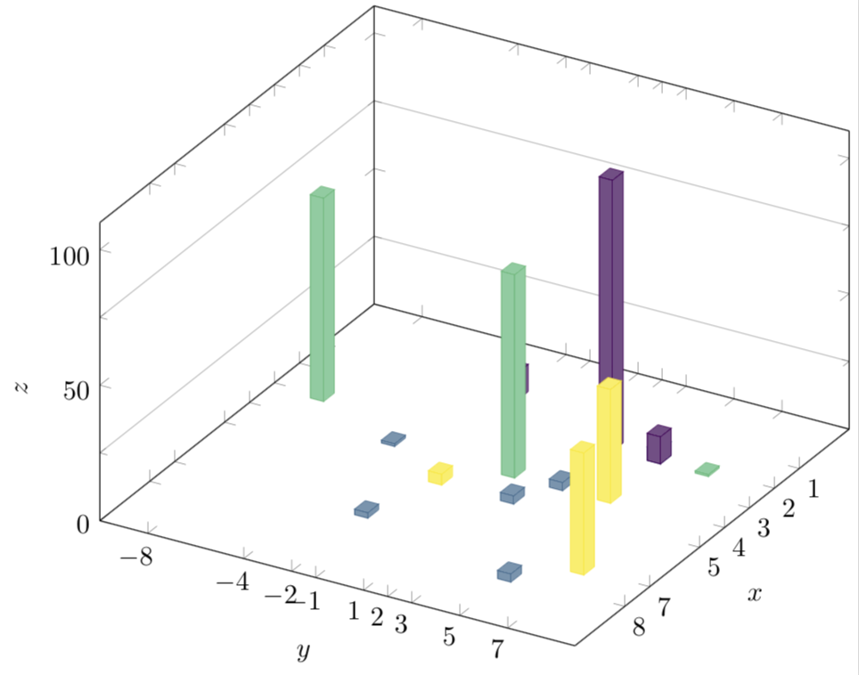
Hier ist ein Vorschlag. pgfplots hat die Möglichkeit, in einem scatter plot Würfel zu zeichnen und man kann die Längen der Kanten ändern. \documentclass[tikz,border=3.14pt]{standalone} \usetikzlibrary{calc} \usepackage{pgfplots} \usepackage{pgfplotstable} \pgfplotsset{compat=1.16} % from https://tex.stackexchange.com/a/102770/121799 \def\pgfplotsinvokeiflessthan#1#2#3#4{% \pgfkeysvalueof{/pgfplots/iflessthan/.@cmd}{#1}{#2}{#3}{#4}\pgfeov }% \def\pgfplotsmulticmpthree#1#2#3#4#5#6\do#7#8{% \pgfplotsset{float <}% \pgfplotsinvokeiflessthan{#1}{#4}{% % first key <: #7% }{% \pgfplotsinvokeiflessthan{#4}{#1}{% % first key >: #8% }{% % first key ==: \pgfplotsset{float <}% \pgfplotsinvokeiflessthan{#2}{#5}{% % second key < #7% }{% \pgfplotsinvokeiflessthan{#5}{#2}{% % second key > #8% }{% % second key == \pgfplotsset{float <}% \pgfplotsinvokeiflessthan{#3}{#6}{% % third key < #7% }{% % third key >= #8% }% }% }% }% }% }% \begin{document} \pgfplotstableread[col sep=comma,header=true]{% x,y,color,myvalue 2,3,1,100 4,3,2,3 2,7,3,0.75 7,7,4,45 8,5,2,3 2,5,1,10 4,-4,2,1 4,1,3,75 5,-1,4,4 5,2,2,3 1,-2,1,10 2,5,2,5 3,-8,3,75 4,5,4,42 7,-2,2,2 }{\datatable} % %\pgfplotstablesort[col sep=comma,header=true]\resulttable{\datatable} \pgfplotstablesort[create on use/sortkey/.style={ create col/assign/.code={% \edef\entry{{\thisrow{x}}{\thisrow{y}}{\thisrow{myvalue}}}% \pgfkeyslet{/pgfplots/table/create col/next content}\entry } }, sort key=sortkey, sort cmp={% iflessthan/.code args={#1#2#3#4}{% \edef\temp{#1#2}% \expandafter\pgfplotsmulticmpthree\temp\do{#3}{#4}% }, }, sort, columns/Mtx/.style={string type}, columns/Kind/.style={string type},]\resulttable{\datatable} \begin{tikzpicture}%[x={(0.866cm,-0.5cm)},y={(0.866cm,0.5cm)},z={(0cm,1 cm)}] \pgfplotsset{set layers} \begin{axis}[% from section 4.6.4 of the pgfplotsmanual view={120}{40}, width=320pt, height=280pt, z buffer=none, xmin=-1,xmax=9, ymin=-10,ymax=8, zmin=0,zmax=200, enlargelimits=upper, ztick={0,100,200}, zticklabels={0,50,100}, % here one has to "cheat" % meaning that one has to put labels which are the actual value % divided by 2. This is because the bars will be centered at these % values xtick=data, extra tick style={grid=major}, ytick=data, grid=minor, xlabel={$x$}, ylabel={$y$}, zlabel={$z$}, minor tick num=1, point meta=explicit, colormap name=viridis, scatter/use mapped color={ draw=mapped color,fill=mapped color!70}, execute at begin plot={} ] \path let \p1=($(axis cs:0,0,1)-(axis cs:0,0,0)$) in \pgfextra{\pgfmathsetmacro{\conv}{2*\y1} \typeout{Kindly\space\space consider\space setting\space the\space prefactor\space of\space z\space to\space \conv}}; \addplot3 [visualization depends on={ 0.9952*z \as \myz}, % you'll get told how to adjust the prefactor scatter/@pre marker code/.append style={/pgfplots/cube/size z=\myz pt},% scatter,only marks, mark=cube*,mark size=5,opacity=1] table[x expr={\thisrow{x}},y expr={\thisrow{y}},z expr={1*\thisrow{myvalue}}, meta expr={\thisrow{color}} ] \resulttable; \end{axis} \end{tikzpicture} \end{document} UPDATE: Mein ursprünglicher Code hatte einen Fehler, die Balken müssen anders sortiert werden. Glücklicherweise bekommt man bei pgfplots die Lösung gleich mitgeliefert. ;-) Der Code spuckt jetzt einen Skalierungsfaktor aus, der eingetragen werden muss, und zwar ist das "Ich habe es nicht geschafft, das zu automatisieren." https://golatex.de/viewtopic.php?f=6&t=19123&p=112434#p112434
(26 Aug '20, 12:54)
cis
|


Das geht nicht ohne vorherige Verarbeitung mit einem externen Programm. Schau mal hier: https://tex.stackexchange.com/questions/52987/3-dimensional-histogram-in-pgfplots