|
Ich hänge bei folgendem Problem: Ich möchte gerne 2 Untereinander angeordnete Bilder kein eigenes subcaption-Label verpassen allerdings in einer gemeinsamen Bildunterschrift Abb. (a) und Abb. (b) beschreiben, wie hier auf Seite 9. (http://ftp.fernuni-hagen.de/ftp-dir/pub/mirrors/www.ctan.org/macros/latex/contrib/caption/subcaption.pdf) Wie bekomme ich nun die Beschriftung (a) und (b) in die Grafik? Die Grafiken sind tikz Plots. Ich würde gerne die Labels oben links in die Ecke positionieren, so dass diese immer den Gleichen Abstand zu dem Rand des Bildes haben. EDIT: Bei mir werden die Beschriftungen a und b nicht an der gewünschten Stelle angezeigt. "Beisst" sich da irgendwas mit den Einstellungen im meinem Code? Des Weiteren würde ich gerne die Beschriftung a und b in Klammern und etwas dicker haben, um diese etwas hervorzuheben. Wo muss ich diese Einstellung vornehmen? In den eckigen Klammern in dem node-Befehl? \documentclass{article} \usepackage[utf8]{inputenc} \usepackage{subcaption} \usepackage{tikz} \usepackage{float} \usepackage{pgfplots} \begin{document} \begin{figure}[H] \centering \begin{subfigure}[t]{0.9\linewidth} \centering \phantomsubcaption \label{fig:sub-a} \begin{tikzpicture}[trim axis left] \begin{axis}[% compat=newest, width=0.95\linewidth, height=6cm, scale=.85, scale only axis, separate axis lines, every outer x axis line/.append style={black}, every x tick label/.append style={font=\color{black}\footnotesize}, every y tick label/.append style={font=\color{black}\footnotesize}, xmin=0, xmax=260, xlabel={Zeit}, ymin=-1, ymax=10, ylabel={Strom}, axis background/.style={fill=white}, scaled ticks=false, y tick label style={/pgf/number format/.cd,use comma,fixed,precision=3}, ylabel near ticks, xlabel near ticks, ] \addplot [color=blue, thick] table[row sep=crcr]{% 7 6.16815\\ 11 6.14285000000001\\ 18 6.10624999999999\\ 21 6.09290000000001\\ 33 6.05430000000001\\ 38 6.0429\\ 40 6.03725\\ 49 6.01849999999999\\ 52 6.01339999999999\\ 56 6.0061\\ 59 6.00149999999999\\ 63 5.99504999999999\\ 73 5.98115000000001\\ 77 5.97604999999999\\ 81 5.97065000000001\\ 85 5.9667\\ 87 5.96369999999999\\ 90 5.96025\\ 127 5.9196\\ 129 5.91659999999999\\ 187 5.85605000000001\\ 194 5.84815\\ 197 5.845\\ 233 5.80500000000001\\ 234 -0.000270000000000437\\ 237 -0.000290000000006785\\ }; \node[below right] at (current bounding box.north west) {\thesubfigure}; \end{axis} \end{tikzpicture} \end{subfigure}\\ \begin{subfigure}[t]{0.9\linewidth} \centering \phantomsubcaption \label{fig:sub-b} \begin{tikzpicture}[trim axis left] \begin{axis}[% compat=newest, width=0.95\linewidth, height=6cm, scale=.85, scale only axis, separate axis lines, every outer x axis line/.append style={black}, every x tick label/.append style={font=\color{black}\footnotesize}, every y tick label/.append style={font=\color{black}\footnotesize}, xmin=0, xmax=260, xlabel={Zeit}, ymin=-1, ymax=10, ylabel={Strom}, axis background/.style={fill=white}, scaled ticks=false, y tick label style={/pgf/number format/.cd,use comma,fixed,precision=3}, ylabel near ticks, xlabel near ticks, ] \addplot [color=blue, thick] table[row sep=crcr]{% 7 6.16815\\ 11 6.14285000000001\\ 18 6.10624999999999\\ 21 6.09290000000001\\ 33 6.05430000000001\\ 38 6.0429\\ 40 6.03725\\ 49 6.01849999999999\\ 52 6.01339999999999\\ 56 6.0061\\ 59 6.00149999999999\\ 63 5.99504999999999\\ 73 5.98115000000001\\ 77 5.97604999999999\\ 81 5.97065000000001\\ 85 5.9667\\ 87 5.96369999999999\\ 90 5.96025\\ 127 5.9196\\ 129 5.91659999999999\\ 187 5.85605000000001\\ 194 5.84815\\ 197 5.845\\ 233 5.80500000000001\\ 234 -0.000270000000000437\\ 237 -0.000290000000006785\\ }; \node[below right] at (current bounding box.north west) {\thesubfigure}; \end{axis} \end{tikzpicture}%\end{subfigure} \end{subfigure} \caption{Beschriftung zu \ref{fig:sub-a} und \ref{fig:sub-b}} \label{fig:Strommessungsgenauigkeit} \end{figure} \end{document} |
|
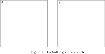
Dazu verwendet man, wie in der Anleitung beschrieben \documentclass{article} \usepackage{subcaption} \usepackage{tikz} \begin{document} \begin{figure} \centering \begin{subfigure}{.5\linewidth} \phantomsubcaption \label{fig:sub-a} \begin{tikzpicture} \draw (0,0) rectangle (5,5); \node[below right] at (current bounding box.north west) {\thesubfigure}; \end{tikzpicture} \end{subfigure}% \begin{subfigure}{.5\linewidth} \phantomsubcaption \label{fig:sub-b} \begin{tikzpicture} \draw (0,0) rectangle (5,5); \node[below right] at (current bounding box.north west) {\thesubfigure}; \end{tikzpicture} \end{subfigure} \caption{Beschriftung zu \ref{fig:sub-a} und \ref{fig:sub-b}} \end{figure} \end{document}
|
|
Ich habe es glaube ich hinbekommen. Ob das die eleganteste Lösung ist, weiß ich allerdings nicht: \node[below right] at (axis description cs:0,1) {(\thesubfigure)}; Damit wird die Beschriftung an dem Koordinatensystem ausgerichtet. |

