|
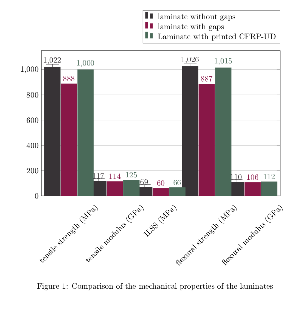
Ich will auf meinem Diagramm errorBars definieren, aber weiß ich nicht, wie ich es machen soll! Kann vielleicht jemand mir helfen? \definecolor{bblack}{HTML}{363033} \definecolor{rred}{HTML}{9f1147} \definecolor{ggreen}{HTML}{356a58} \begin{figure}[H] \begin{tikzpicture} \begin{axis}[ width = 1*\textwidth, height = 8cm, major x tick style = transparent, ybar=2*\pgflinewidth, bar width=20pt, ymajorgrids = true, % ylabel = {s}, symbolic x coords={tensile strength (MPa),tensile modulus (GPa),ILSS (MPa),flexural strength (MPa),flexural modulus (GPa)}, xtick = data, x tick label style={rotate=45}, nodes near coords, nodes near coords align={vertical}, scaled y ticks = false, enlarge x limits=0.15, ymin=0, legend cell align=left, legend style={ at={(1,1.05)}, anchor=south east, column sep=1ex } ] \addplot[style={bblack,fill=bblack,mark=none}] coordinates {(tensile strength (MPa),1022) (tensile modulus (GPa),117) (ILSS (MPa),69) (flexural strength (MPa),1026) (flexural modulus (GPa),110)}; \addplot[style={rred,fill=rred,mark=none}] coordinates {(tensile strength (MPa),888) (tensile modulus (GPa),114) (ILSS (MPa),60) (flexural strength (MPa),887) (flexural modulus (GPa),106)}; \addplot[style={ggreen,fill=ggreen,mark=none}] coordinates {(tensile strength (MPa),1000) (tensile modulus (GPa),125) (ILSS (MPa),66) (flexural strength (MPa),1015) (flexural modulus (GPa),112)}; \legend{laminate without gaps,laminate with gaps,Laminate with printed CFRP-UD} \end{axis} \end{tikzpicture} \caption{Comparison of the mechanical properties of the laminates} \label{material-properties} \end{figure} |
|
Ich habe keine Ahnung, wie gross Deine Fehler sind, also habe ich einen Fantasie-Wert benutzt. Und Deine Balken überlappen, an Deiner Stelle würde ich das ändern. \documentclass{article} \usepackage{pgfplots} \pgfplotsset{compat=1.16} \begin{document} \definecolor{bblack}{HTML}{363033} \definecolor{rred}{HTML}{9f1147} \definecolor{ggreen}{HTML}{356a58} \begin{figure}[h] \begin{tikzpicture} \begin{axis}[ width = 1*\textwidth, height = 8cm, major x tick style = transparent, ybar=2*\pgflinewidth, bar width=20pt, %<- das wuerde ich aendern ymajorgrids = true, % ylabel = {s}, symbolic x coords={tensile strength (MPa),tensile modulus (GPa),ILSS (MPa),flexural strength (MPa),flexural modulus (GPa)}, xtick = data, x tick label style={rotate=45}, nodes near coords, nodes near coords align={vertical}, scaled y ticks = false, enlarge x limits=0.15, ymin=0, legend cell align=left, legend style={ at={(1,1.05)}, anchor=south east, column sep=1ex } ] \addplot[style={bblack,fill=bblack,mark=none},error bars/.cd, y dir=both,y fixed=20, error mark options={ rotate=90, mark size=8pt, }] coordinates {(tensile strength (MPa),1022) (tensile modulus (GPa),117) (ILSS (MPa),69) (flexural strength (MPa),1026) (flexural modulus (GPa),110)}; \addplot[style={rred,fill=rred,mark=none}] coordinates {(tensile strength (MPa),888) (tensile modulus (GPa),114) (ILSS (MPa),60) (flexural strength (MPa),887) (flexural modulus (GPa),106)}; \addplot[style={ggreen,fill=ggreen,mark=none}] coordinates {(tensile strength (MPa),1000) (tensile modulus (GPa),125) (ILSS (MPa),66) (flexural strength (MPa),1015) (flexural modulus (GPa),112)}; \legend{laminate without gaps,laminate with gaps,Laminate with printed CFRP-UD} \end{axis} \end{tikzpicture} \caption{Comparison of the mechanical properties of the laminates} \label{material-properties} \end{figure} \end{document} Wie Du siehst, habe ich nur im ersten 1
@cis Klar, Danke! Kann ich alles gerne machen wenn ich weiss wohin die Reise geht. Man muss evtl. auch die
(16 Mai '18, 17:18)
Community
|


Könntest Du bitte Deinen als Spaghetti-Code formatierten Code-Schnipsel zu einem Minimalbeispiel erweitern? Also ein möglichst kurzes, aber komplettes Dokument, von
\documentclass{...}bis zu\end{document}, welches das Problem zeigt, einfügen. Das vereinfacht die Bearbeitung erheblich und ist meist eine Garantie für eine Lösung. Optimal wäre, wenn Du dabei neben der korrekten Markdown-Formatierung auch noch ein wenig auf semantische Einrückungen achten könntest, um den Code lesbar zu gestalten.In Ermangelung eines vollständigen Minimalsbeispiels sei lediglich vorsorglich auf Abschnitt 4.12.1 der aktuellen
pgfplots-Anleitung, »Input Formats of Error Coordinates« hingewiesen.