|
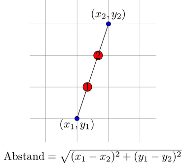
Entlang einer Linie sollen gleichmäßig nodes platziert werden (so ähnlich wie bei Objekte entlang einer Geraden äquidistant anordnen und Wie kann ich TikZ-Knoten im Kreis anordnen?). Die Frage ist, wie aus den x- und y-Koordinaten der Endpunkte von einer Geraden die nodes-Positionen ausgerechnet werden können. Hier ein Beispiel für 2 nodes: \documentclass{standalone} \usepackage[utf8]{inputenc} \usepackage[ngerman]{babel} \usepackage[T1]{fontenc} \usepackage{lmodern} \usepackage{amsmath} \usepackage{tikz} \begin{document} \begin{tikzpicture} \draw[help lines] (-1.5,-0.75) grid (2.5,3.75); \draw[fill=blue] (0,0) node[yshift=-0.2cm] {$(x_1,y_1)$} circle (2pt) -- (1,3) node[yshift=0.3cm] {$(x_2,y_2)$} circle (2pt) ; \draw[fill=red] (0.33,1) circle (4pt) node {1}; \draw[fill=red] (0.67,2) circle (4pt) node {2}; % Abstand Geraden-Endpunkte \draw (0.5,-1.2) node {$\text{Abstand}=\sqrt{(x_1-x_2)^2+(y_1-y_2)^2}$}; \end{tikzpicture} \end{document}
|
|
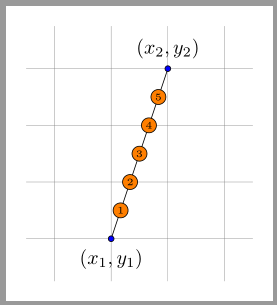
Ergänzend zur Antwort von @Henri ist hier mal noch eine Variante bei der unter Verwendung von \documentclass[margin=10pt]{standalone} \usepackage{tikz} \begin{document} \begin{tikzpicture}[ dot/.style={circle,draw,fill=#1,inner sep=1pt,font=\tiny}, dot/.default=white ] \draw[help lines] (-1.5,-0.75) grid (2.5,3.75); \draw (0,0)node[dot=blue,label={below:$(x_1,y_1)$}]{}-- (1,3)node[dot=blue,label={above:$(x_2,y_2)$}]{} node foreach \i in {1,...,5}[pos={1/(5+1)*\i},dot=orange]{\i}; \end{tikzpicture} \end{document}
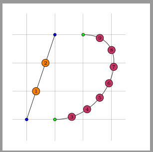
Und noch eine weitere Variante mit der \documentclass[margin=10pt]{standalone} \usepackage{tikz} \usetikzlibrary{decorations.markings} \newcounter{markcounter} \begin{document} \begin{tikzpicture}[ dot/.style={circle,draw,fill=#1,inner sep=1pt,font=\tiny}, dot/.default=white, dotfillcolor/.style={dot/.append style={fill=#1}}, mymarks/.style={ decoration={ markings, mark= between positions {1/(#1+1)} and {#1/(#1+1)} step {1/(#1+1)} with{\stepcounter{markcounter}\node[dot]{\themarkcounter};} },decorate } ] \draw[help lines] (-1.5,-0.75) grid (2.5,3.75); \draw[postaction={dotfillcolor=orange,mymarks=2}] (-1,0)node[dot=blue]{}--(0,3)node[dot=blue]{}; \draw[postaction={dotfillcolor=purple!80,mymarks=7}] (0,0)node[dot=green]{}.. controls (2,0) and (3,3) ..(1,3)node[dot=green]{}; \end{tikzpicture} \end{document}
|
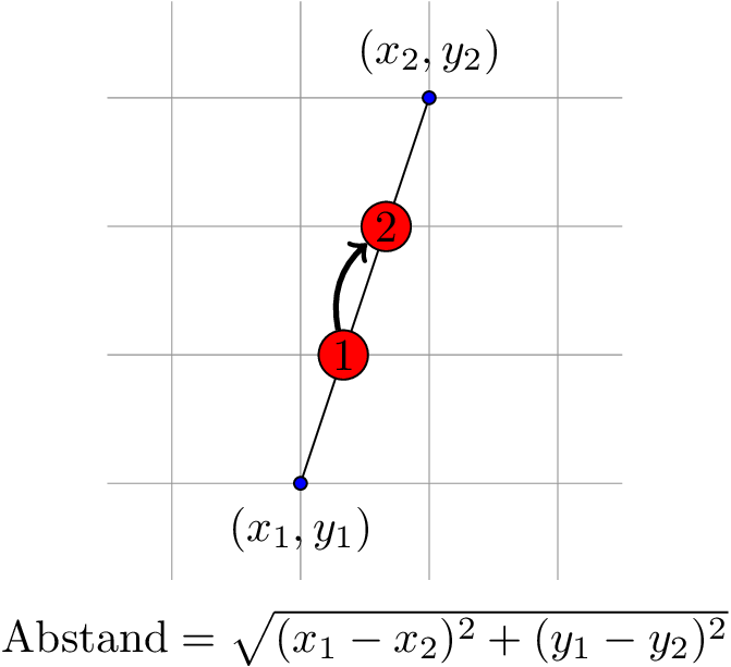
Nodes entlang des PfadesWenn es nur darum geht die Punkte zu referenzieren ohne unbedingt die Koordinaten zu kennen kann ich nur empfehlen die Nodes einfach auf der Linie zu platzieren und mittels \documentclass[tikz]{standalone} \usepackage{mathtools} \begin{document} \begin{tikzpicture}[ dot/.style={draw,fill=#1,circle,inner sep=1pt}, dot/.default=black, ] \draw[help lines] (-1.5,-0.75) grid (2.5,3.75); \draw[fill=blue] (0,0) node[dot=blue,label={below:$(x_1,y_1)$}] {} -- node[pos=.333,dot=red] (n1) {1} node[pos=.666,dot=red] (n2) {2} (1,3) node[dot=blue,label={above:$(x_2,y_2)$}] {}; % Abstand Geraden-Endpunkte \draw (0.5,-1.2) node {$\text{Abstand}=\sqrt{(x_1-x_2)^2+(y_1-y_2)^2}$}; % Beispiel fürs referenzieren \draw[very thick,->] (n1) to[bend left] (n2); \end{tikzpicture} \end{document} letMit Hilfe der Bibliothek \documentclass[tikz]{standalone} \usetikzlibrary{calc} \usepackage{mathtools} \begin{document} \begin{tikzpicture}[ dot/.style={draw,fill=#1,circle,inner sep=1pt}, dot/.default=black, ] \draw[help lines] (-1.5,-0.75) grid (2.5,3.75); \draw[fill=blue] (0,0) node[dot=blue,label={below:$(x_1,y_1)$}] {} -- (1,3) node[dot=blue,label={above:$(x_2,y_2)$}] {}; \path let \p1 = (0,0), \p2 = (1,3), \n1 = {veclen(\x1,\x2)}, \n2 = {veclen(\y1,\y2)} in (\n1/3,\n2/3) node[dot=red] {1} (2*\n1/3,2*\n2/3) node[dot=red] {2}; % Abstand Geraden-Endpunkte \draw (0.5,-1.2) node {$\text{Abstand}=\sqrt{(x_1-x_2)^2+(y_1-y_2)^2}$}; \end{tikzpicture} \end{document} decorations.markingsDie \documentclass[tikz]{standalone} \usetikzlibrary{decorations.markings} \usepackage{mathtools} \begin{document} \begin{tikzpicture}[ dot/.style={draw,fill=#1,circle,inner sep=1pt}, dot/.default=black, ] \draw[help lines] (-1.5,-0.75) grid (2.5,3.75); \draw[fill=blue,decoration={% markings, mark=at position .333 with {\node[dot=red] {1};}, mark=at position .666 with {\node[dot=red] {2};} },postaction=decorate] (0,0) node[dot=blue,label={below:$(x_1,y_1)$}] {} -- (1,3) node[dot=blue,label={above:$(x_2,y_2)$}] {}; % Abstand Geraden-Endpunkte \draw (0.5,-1.2) node {$\text{Abstand}=\sqrt{(x_1-x_2)^2+(y_1-y_2)^2}$}; \end{tikzpicture} \end{document} |


