|
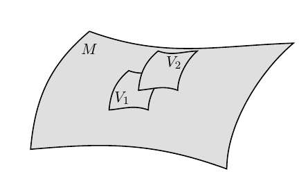
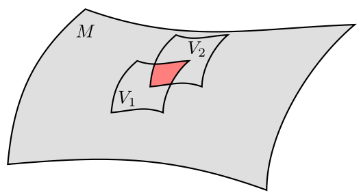
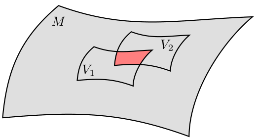
Verwandt mit http://texwelt.de/wissen/fragen/17099/wie-erstelle-ich-ein-individuelles-band-in-tikz Ich möchte die Schnittfläche von Karte1 (= V1) und Karte2 (= V2) färben; allerdings entsteht Karte2 als Verschiebung von Karte1. Gibt es dafür eine einfache Möglichkeit?
%\documentclass[margin=5pt, varwidth]{standalone} \documentclass{scrreprt} \usepackage[utf8]{inputenc} \usepackage[ngerman]{babel} \usepackage{tikz} \usetikzlibrary{positioning} \usepackage{amsmath} %\usetikzlibrary{shapes} \begin{document} \begin{tikzpicture}%[overlay] % Raum \coordinate (Ma) at (0,0); \coordinate (Mb) at (5,-.5); %\coordinate[right below = 5cm and -0.5cm of Ma] (Mb) ; \coordinate (Mc) at (6.7,2.7); \coordinate (Md) at (1.5,3); \path [thick,draw,fill=lightgray!50] (Ma) to [out=5,in=160] (Mb) to [out=90, in=220,looseness=.8] (Mc) to [out=182, in=340] (Md) node[below=5pt]{$M$} to [out=220,in=85](Ma) -- cycle ; % Karte \coordinate (Va) at (2,1); \coordinate (Vb) at (3,1); \coordinate (Vc) at (3.5,2); \coordinate (Vd) at (2.5,2); \tikzset{c/.style={every coordinate/.try}} \def\Karte{% \path [thick,draw,fill=lightgray!50] ([c]Va) to [out=5,in=160] ([c]Vb) to [out=90, in=220,looseness=.8] ([c]Vc) to [out=182, in=340] ([c]Vd) to [out=220,in=85]([c]Va) -- cycle ; } %Karte1 %\draw[] (Va) -- (Vb) -- (Vc) -- (Vd) -- cycle; \Karte \node[above right] at (Va) {$V_1$}; % Karte2 \begin{scope}[every coordinate/.style={shift={(0.75,0.5)}}] %\draw[red] ([c]Va) -- ([c]Vb) -- ([c]Vc) -- ([c]Vd) -- cycle; \Karte \node[left=17pt, below] at ([c]Vc) {$V_2$}; \end{scope} \end{tikzpicture} \end{document} |
|
Eine Möglichkeit ist die Nutzung von \documentclass[margin=5pt]{standalone} \usepackage{tikz} \begin{document} \begin{tikzpicture} % Raum \coordinate (Ma) at (0,0); \coordinate (Mb) at (5,-.5); \coordinate (Mc) at (6.7,2.7); \coordinate (Md) at (1.5,3); \path [thick,draw,fill=lightgray!50] (Ma) to [out=5,in=160] (Mb) to [out=90, in=220,looseness=.8] (Mc) to [out=182, in=340] (Md) node[below=5pt]{$M$} to [out=220,in=85] (Ma) -- cycle ; % Karte \newcommand\Karte[1]{% \coordinate (Va) at (2,1); \coordinate (Vb) at (3,1); \coordinate (Vc) at (3.5,2); \coordinate (Vd) at (2.5,2); \path [#1] (Va) to [out=5,in=160] (Vb) to [out=90, in=220,looseness=.8] (Vc) to [out=182, in=340] (Vd) to [out=220,in=85] (Va) -- cycle ; } % Füllung \begin{scope} \Karte{clip} \begin{scope}[shift={(0.75,0.5)}] \Karte{fill=red!50} \end{scope} \end{scope} % Karte1 \Karte{draw,thick} \node[above right] at (Va) {$V_1$}; % Karte2 \begin{scope}[shift={(0.75,0.5)}] \Karte{draw,thick} \node[left=17pt, below] at (Vc) {$V_2$}; \end{scope} \end{tikzpicture} \end{document} Ergebnis:
Mit dem Vorschlag von hier, der auf der Antwort von cfeuersaenger auf die Frage Wie kann ich die Fläche zwischen mehreren Pfaden füllen basiert, wäre eine weitere Möglichkeit: \documentclass[margin=5pt]{standalone} \usepackage{pgfplots} \pgfplotsset{compat=1.13} \usepgfplotslibrary{fillbetween} \begin{document} \begin{tikzpicture} \pgfdeclarelayer{post main} \pgfsetlayers{main,post main} % Raum \coordinate (Ma) at (0,0); \coordinate (Mb) at (5,-.5); \coordinate (Mc) at (6.7,2.7); \coordinate (Md) at (1.5,3); \path [thick,draw,fill=lightgray!50] (Ma) to [out=5,in=160] (Mb) to [out=90, in=220,looseness=.8] (Mc) to [out=182, in=340] (Md) node[below=5pt]{$M$} to [out=220,in=85] (Ma) -- cycle ; % Karte \newcommand\Karte[1]{% \coordinate (Va) at (2,1); \coordinate (Vb) at (3,1); \coordinate (Vc) at (3.5,2); \coordinate (Vd) at (2.5,2); \path [name path global=#1,thick,draw] (Va) to [out=5,in=160] (Vb) to [out=90, in=220,looseness=.8] (Vc) to [out=182, in=340] (Vd) to [out=220,in=85] (Va) -- cycle ; } \pgfonlayer{post main} % Karte1 \Karte{Karte1} \node[above right] at (Va) {$V_1$}; % Karte2 \begin{scope}[shift={(0.75,0.5)}] \Karte{Karte2} \node[left=17pt, below] at (Vc) {$V_2$}; \end{scope} \endpgfonlayer \path[%draw=blue,line width=1mm, fill=red!50, intersection segments={ of=Karte1 and Karte2, sequence={L2--R1} } ]; \end{tikzpicture} \end{document} Das schwierigste daran ist die Auswahl und Richtung der Segmente für Wenn die Formen alle ähnlich sein sollen, könnte man sich dafür auch ein \documentclass[margin=5pt]{standalone} \usepackage{pgfplots} \pgfplotsset{compat=1.13} \usepgfplotslibrary{fillbetween} \begin{document} \begin{tikzpicture} \pgfdeclarelayer{post main} \pgfsetlayers{main,post main} \tikzset{ Band/.pic={ \path [ name path global=#1, pic actions, thick, shorten <=-.45*\pgflinewidth,shorten >=-.45*\pgflinewidth ] (0,0)coordinate(-a) to [out=5,in=160] (5,-.5)coordinate(-b) to [out=90, in=220,looseness=.8] (6.7,2.7)coordinate(-c) to [out=182, in=340] (1.5,3)coordinate(-d) to [out=220,in=85] (-a) ; } } \pic[draw,fill=lightgray!50](Raum){Band=Raum}; \node[below=5pt]at(Raum-d){$M$}; \pgfonlayer{post main} \pic[draw,scale=.3](K1)at(2,1){Band=Karte1}; \node[above right] at (K1-a) {$V_1$}; \pic[draw,scale=.3](K2)at(3,1.4){Band=Karte2}; \node[left=17pt, below] at (K2-c) {$V_2$}; \endpgfonlayer \path[fill=red!50, intersection segments={ of=Karte1 and Karte2, sequence={L2--R1} } ]; \end{tikzpicture} \end{document} Ergebnis:
Sehr schön! :()
(21 Apr '16, 22:27)
cis
|


