
|
Hallo, ich würde gerne in diesem Code den Transformator node (T) [transformer core,below right=0mm and 17mm]{}
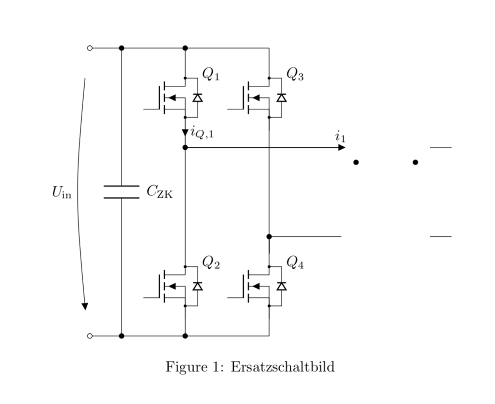
ausblenden. Dabei sollen die von "transformer core" abhängigen Koordiaten nicht verändert werden. Daher kann ich das Bateil nicht einfach aus dem COde entfernen, da sonst das Gesatmbild nicht mehr funktioniert. Die Idee ist, dass nur die Zuleitung am Ende sichtbar sind, und der Rest abgeschnitten wird. Danke. \documentclass{article} \usepackage[utf8]{inputenc} \usepackage[siunitx,fetbodydiode,smartlabels]{circuitikz} \usetikzlibrary{positioning} \begin{document} \begin{figure} \centering % Based on a template by Erno Pentzin (2013), http://www.texample.net/tikz/examples/ac-drive-components/; based on suggestions from tex.stackexchange, https://tex.stackexchange.com/questions/395535/some-help-with-connections-and-voltage-arrow-in-circuitikz#395561 % Based on a template by Erno Pentzin (2013), http://www.texample.net/tikz/examples/ac-drive-components/; based on suggestions from tex.stackexchange, https://tex.stackexchange.com/questions/395535/some-help-with-connections-and-voltage-arrow-in-circuitikz#395561 \begin{circuitikz}[lbl/.style = {label={[label distance=4mm]above right:#1}}] % this line defines a new style to alter the distance of labels, mosfets due to diode and transformer label \draw % top part of switch legs (0,0) coordinate (s1) to ++ (0,-0.4) %node (mosfet1) [nigfete,below,anchor=D] {$Q_1$} % old, label distance incorrect node (mosfet1) [nigfete,below,anchor=D,lbl=$Q_1$] {} % new, label distance ok (mosfet1) node (mosfet3) [nigfete,right=10mm,lbl=$Q_3$] {} % This is the only variable that needs to be changed to adjust the distance from Q1/Q2 to Q3/Q4 (mosfet1.S) to [short,current/distance = 0.1,i=$i_{Q,1}$,-*] ++ (0,-0.4) coordinate (t1) % transformer (t1 -| mosfet3.S) coordinate (hilf1) % Connect Q1 with Q3S which is electrically wrong, but easier to draw node (T) [transformer core,below right=0mm and 17mm]{} % This is the only variable that needs to be changed to adjust the distance from Transformer T from node t1 (underneath Q1) (T.base) node[label=above:$N_1\quad N_2$]{} node[circ] (E) at ($(T.A1)+(0.35,-0.35)$) {} % Wicklungssinn T node[circ] (F) at ($(T.B1)+(-0.35,-0.35)$) {} % Wicklungssinn T % bottom part of switch legs (mosfet3.S |- T.A2) coordinate (t2) % likewise counter intuitive to ++ (0,-0.4) node (mosfet4) [nigfete,below,anchor=D,lbl=$Q_4$] {} (t1 |- mosfet4.D) node (mosfet2) [nigfete,below,anchor=D,lbl=$Q_2$] {} % connection lines origins at transformer %(T.A1) to (t1) % old, replaced by short b/c current arrows, see below (t1) to [short,current/distance = 1,i=$i_1$] (T.A1) (T.A2) to [short,-*] (t2) (T.B1) to [short] ++ (0.5,0) coordinate (t3) (T.B2) to [short] ++ (0.5,0) coordinate (t4) % connection lines orign at mosfet (t1) to (mosfet2.D) (mosfet2.S) to ++ (0,-0.4) coordinate (s2) (mosfet3.D) to ++ (0, 0.4) coordinate (s3) (mosfet3.S) to (mosfet4.D) (mosfet4.S) to ++ (0,-0.4) coordinate (s4) % supply lines (s3) -- (s1) to [short,*-] ++(-1.5,0) coordinate (czk+) to [short,*-o] ++ (-0.75,0) coordinate (s+) % added *-o, * to get dot at S1 (s4) -- (s2) to [short,*-] ++(-1.5,0) coordinate (czk-) to [short,*-o] ++ (-0.75,0) coordinate (s-) % added *-o, * to get dot at S2 % (s+) to [open, v=60<\volt>, invert] (s-) % old, with SI unit (s+) to [open, v=$U_{\mathrm{in}}$, invert] (s-) % new, with variable U_in % missing C_ZK inserted (czk+) to [C,l=$C_{\mathrm{ZK}}$] (czk-) ; \end{circuitikz} \caption[Ersatzschaltbild]{Ersatzschaltbild} \label{fig:ersatzschaltbild} \end{figure} \end{document} |
|
Ich bin jederzeit bereit, diese Antwort zu löschen. Man kann beliebige nodes mit \documentclass{article} \usepackage[utf8]{inputenc} \usepackage[siunitx,fetbodydiode,smartlabels]{circuitikz} \usetikzlibrary{positioning} \begin{document} \begin{figure} \centering % Based on a template by Erno Pentzin (2013), http://www.texample.net/tikz/examples/ac-drive-components/; based on suggestions from tex.stackexchange, https://tex.stackexchange.com/questions/395535/some-help-with-connections-and-voltage-arrow-in-circuitikz#395561 % Based on a template by Erno Pentzin (2013), http://www.texample.net/tikz/examples/ac-drive-components/; based on suggestions from tex.stackexchange, https://tex.stackexchange.com/questions/395535/some-help-with-connections-and-voltage-arrow-in-circuitikz#395561 \begin{circuitikz}[lbl/.style = {label={[label distance=4mm]above right:#1}}] % this line defines a new style to alter the distance of labels, mosfets due to diode and transformer label \draw % top part of switch legs (0,0) coordinate (s1) to ++ (0,-0.4) %node (mosfet1) [nigfete,below,anchor=D] {$Q_1$} % old, label distance incorrect node (mosfet1) [nigfete,below,anchor=D,lbl=$Q_1$] {} % new, label distance ok (mosfet1) node (mosfet3) [nigfete,right=10mm,lbl=$Q_3$] {} % This is the only variable that needs to be changed to adjust the distance from Q1/Q2 to Q3/Q4 (mosfet1.S) to [short,current/distance = 0.1,i=$i_{Q,1}$,-*] ++ (0,-0.4) coordinate (t1) % transformer (t1 -| mosfet3.S) coordinate (hilf1) % Connect Q1 with Q3S which is electrically wrong, but easier to draw node (T) [opacity=0,transformer core,below right=0mm and 17mm]{} % This is the only variable that needs to be changed to adjust the distance from Transformer T from node t1 (underneath Q1) (T.base) node[label={[opacity=0]above:$N_1\quad N_2$}]{} node[circ] (E) at ($(T.A1)+(0.35,-0.35)$) {} % Wicklungssinn T node[circ] (F) at ($(T.B1)+(-0.35,-0.35)$) {} % Wicklungssinn T % bottom part of switch legs (mosfet3.S |- T.A2) coordinate (t2) % likewise counter intuitive to ++ (0,-0.4) node (mosfet4) [nigfete,below,anchor=D,lbl=$Q_4$] {} (t1 |- mosfet4.D) node (mosfet2) [nigfete,below,anchor=D,lbl=$Q_2$] {} % connection lines origins at transformer %(T.A1) to (t1) % old, replaced by short b/c current arrows, see below (t1) to [short,current/distance = 1,i=$i_1$] (T.A1) (T.A2) to [short,-*] (t2) (T.B1) to [short] ++ (0.5,0) coordinate (t3) (T.B2) to [short] ++ (0.5,0) coordinate (t4) % connection lines orign at mosfet (t1) to (mosfet2.D) (mosfet2.S) to ++ (0,-0.4) coordinate (s2) (mosfet3.D) to ++ (0, 0.4) coordinate (s3) (mosfet3.S) to (mosfet4.D) (mosfet4.S) to ++ (0,-0.4) coordinate (s4) % supply lines (s3) -- (s1) to [short,*-] ++(-1.5,0) coordinate (czk+) to [short,*-o] ++ (-0.75,0) coordinate (s+) % added *-o, * to get dot at S1 (s4) -- (s2) to [short,*-] ++(-1.5,0) coordinate (czk-) to [short,*-o] ++ (-0.75,0) coordinate (s-) % added *-o, * to get dot at S2 % (s+) to [open, v=60<\volt>, invert] (s-) % old, with SI unit (s+) to [open, v=$U_{\mathrm{in}}$, invert] (s-) % new, with variable U_in % missing C_ZK inserted (czk+) to [C,l=$C_{\mathrm{ZK}}$] (czk-) ; \end{circuitikz} \caption[Ersatzschaltbild]{Ersatzschaltbild} \label{fig:ersatzschaltbild} \end{figure} \end{document}
Ich sollte aber dazu sagen, dass mir nicht klar ist, was Alles ausgeblendet werden soll, und, was evtl. wichtiger ist, was die Aussage "Daher kann ich das Bauteil nicht einfach aus dem Code entfernen, da sonst das Gesamtbild nicht mehr funktioniert." genau bedeutet. |

Du kannst jede node mit
opacity=0ausblenden, z.B.node (T) [opacity=0,transformer core,below right=0mm and 17mm]{}@Murmeltier: Ich denke, das könnte durchaus bereits eine Antwort sein.