
|
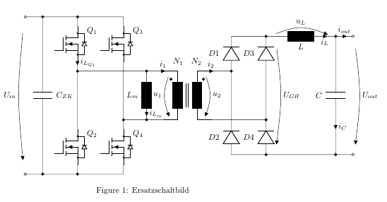
Hallo, wie kann ich im folgenden Cirkuitiz Mosfets (in diesem Fall Q3 und Q4) durch Kapatzitäten (C) ersetzen? Ich habe versucht, einfach nigfete durch C zu ersetzen, aber die Modelle sind natürlich unterschiedlich groß und es gibt keine Ankerpunkte Source und Gate wie beim MOSFET und daher funktioniert das nicht. Wie geht so etwas am einfachsten \documentclass{article} \usepackage[utf8]{inputenc} \usepackage[siunitx,european,fetbodydiode,smartlabels]{circuitikz} \usetikzlibrary{positioning} \begin{document} \begin{figure} % Generalized diagram of different components inside an AC drive with voltage intermediate circuit % Based on a template by % Author: Erno Pentzin (2013), http://www.texample.net/tikz/examples/ac-drive-components/ % Based on a template by Erno Pentzin (2013), http://www.texample.net/tikz/examples/ac-drive-components/; based on suggestions from tex.stackexchange, https://tex.stackexchange.com/questions/395535/some-help-with-connections-and-voltage-arrow-in-circuitikz#395561 \begin{circuitikz}[lbl/.style = {label={[label distance=4mm]above right:#1}}] % this line defines a new style to alter the distance of labels, mosfets due to diode and transformer label \draw % top part of switch legs (0,0) coordinate (s1) to ++ (0,-0.4) %node (mosfet1) [nigfete,below,anchor=D] {$Q_1$} % old, label distance incorrect node (mosfet1) [nigfete,below,anchor=D,lbl=$Q_1$] {} % new, label distance ok (mosfet1) node (mosfet3) [nigfete,right=10mm,lbl=$Q_3$] {} % This is the only variable that needs to be changed to adjust the distance from Q1/Q2 to Q3/Q4 (mosfet1.S) to [short,current/distance = 0.1,i=$i_{L_{Q_1}}$,-*] ++ (0,-0.4) coordinate (t1) % transformer (t1 -| mosfet3.S) coordinate (hilf1) % Connect Q1 with Q3S which is electrically wrong, but easier to draw node (T) [transformer core,below right=0mm and 17mm]{} % This is the only variable that needs to be changed to adjust the distance from Transformer T from node t1 (underneath Q1) (T.base) node[label=above:$N_1\quad N_2$]{} node[circ] (E) at ($(T.A1)+(0.35,-0.35)$) {} % Wicklungssinn T node[circ] (F) at ($(T.B1)+(-0.35,-0.35)$) {} % Wicklungssinn T % bottom part of switch legs (mosfet3.S |- T.A2) coordinate (t2) % likewise counter intuitive to ++ (0,-0.4) node (mosfet4) [nigfete,below,anchor=D,lbl=$Q_4$] {} (t1 |- mosfet4.D) node (mosfet2) [nigfete,below,anchor=D,lbl=$Q_2$] {} % connection lines origins at transformer %(T.A1) to (t1) % old, replaced by short b/c current arrows, see below (t1) to [short,current/distance = 1,i=$i_1$] (T.A1) (T.A2) to [short,-*] (t2) (T.B1) to [short] ++ (0.5,0) coordinate (t3) (T.B2) to [short] ++ (0.5,0) coordinate (t4) % connection lines orign at mosfet (t1) to (mosfet2.D) (mosfet2.S) to ++ (0,-0.4) coordinate (s2) (mosfet3.D) to ++ (0, 0.4) coordinate (s3) (mosfet3.S) to (mosfet4.D) (mosfet4.S) to ++ (0,-0.4) coordinate (s4) % supply lines (s3) -- (s1) to [short,*-] ++(-1.5,0) coordinate (czk+) to [short,*-o] ++ (-0.75,0) coordinate (s+) % added *-o, * to get dot at S1 (s4) -- (s2) to [short,*-] ++(-1.5,0) coordinate (czk-) to [short,*-o] ++ (-0.75,0) coordinate (s-) % added *-o, * to get dot at S2 % (s+) to [open, v=60<\volt>, invert] (s-) % old, with SI unit (s+) to [open, v=$U_{in}$, invert] (s-) % new, with variable U_in % secondary side dc rectifier (t3) to[short,current/distance = -1.5,i=$i_2$,-*] ++(0.35,0) coordinate (AA) % move transformer outlet a bit to the right (t4) to[short,-*] ++(1.85,0) coordinate (BB) % move transformer outlet a bit to the right (AA) to [Do,name=d1,l=$D1$] ++(0,1.5) to[short,-*] ++(1.5,0) coordinate (c1) (AA) -- (AA |- BB) to [Do,invert,name=d2,l_=$D2$] ++(0,-1.5) to[short,-*] ++(1.5,0) coordinate (c2) (BB) -- (BB |- AA) to [Do,name=d3,l=$D3$](c1) (BB) to [Do,invert,name=d4,l_=$D4$](c2) % missing C_ZK inserted (czk+) to [C,l=$C_{ZK}$] (czk-) % missing L_m insterted (hilf1) ++ (1,0) coordinate (hilf2) (t2) ++ (1,0) coordinate (hilf3) (hilf2) to[L,l_=$L_m$,-*,current/distance = 0.45,i=$i_{L_m}$,*-*] (hilf3) % secondary side, L, C, out (c1) to[L,l_=$L$,-*,i_=$i_L$,v^=$u_L$] ++(3,0) coordinate(c3) to[short,i=$i_{out}$,-o] ++(0.75,0) coordinate (out1) (c3) to[C,l_=$C$,i=$i_{C}$,-*] (c3 |- c2) coordinate (c4) -- (c2) (c4) to[short,-o] ++(0.75,0) coordinate (out2) % voltage arrows primary ($(T.A1)+(0.35,0)$) to [open,v=$u_1$] ($(T.A2)+(0.35,0)$) % voltage arrows secondary (out1) to[open, v^=$U_{out}$] (out2) % delete later, voltage arrow %(c1) to[open,v^=$u_L$] (c3) % optional instead voltage arrow of L, from c1 to c3 ($(c1)+(0.35,0)$) to[open,v^=$U_{GR}$] ($(c2)+(0.35,0)$) ($(T.B1)-(0.35,0)$) to [open,v^=$u_2$] ($(T.B2)-(0.35,0)$) ; \end{circuitikz} \caption[Ersatzschaltbild]{Ersatzschaltbild} \label{fig:ersatzschaltbild} \end{figure} \end{document}
|
|
Dieser Code ist mindestens wirr, höchstens chaotisch. Es gibt kein Gesetz, die gesamte Schaltung mit Gewalt in ein einziges Bastel Dir ein Schaltbrett und zeichne Deine Schaltungen sinnvoll aufgeteilt in Schaltkreise. Das Problem hier ist, dass Um diesen durcheinander strukturierten Code noch halbwegs einfach zu hacken, sehe ich nur die Möglichkeit, die Änderung % Alt ========================== % node (mosfet3) [nigfete,right=13mm,lbl=$Q3$] {} % This is the only variable that needs to be changed to adjust the distance from Q1/Q2 to Q3/Q4 % (mosfet1.S) %% Neu ======================== node[white] (mosfet3) [nigfete,right=13mm,lbl=$$] {} % This is the only variable that needs to be changed to adjust the distance from Q1/Q2 to Q3/Q4 (mosfet1.S) % ============================
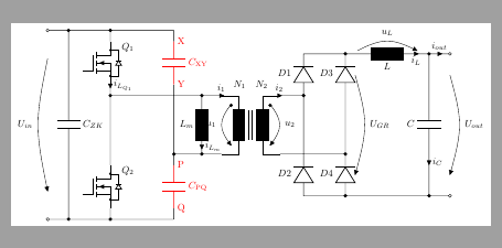
\coordinate[label={[red]right:X}](X) at (mosfet3.D);
\coordinate[label={[red]right:Y}](Y) at (mosfet3.S);
\draw[red] (X) to[C=$C_\text{XY}$] (Y);
\documentclass[margin=5pt, multi=circuitikz]{standalone} \usepackage[siunitx,european,fetbodydiode,smartlabels]{circuitikz} \usetikzlibrary{positioning} \begin{document} \begin{circuitikz}[lbl/.style = {label={[label distance=4mm]above right:#1}}] % this line defines a new style to alter the distance of labels, mosfets due to diode and transformer label \draw[] % top part of switch legs (0,0) coordinate (s1) to ++ (0,-0.4) %node (mosfet1) [nigfete,below,anchor=D] {$Q_1$} % old, label distance incorrect node (mosfet1) [nigfete,below,anchor=D,lbl=$Q_1$] {} % new, label distance ok (mosfet1) % Alt ========================== % node (mosfet3) [nigfete,right=13mm,lbl=$Q3$] {} % This is the only variable that needs to be changed to adjust the distance from Q1/Q2 to Q3/Q4 % (mosfet1.S) %% Neu ======================== node[white] (mosfet3) [nigfete,right=13mm,lbl=$$] {} % This is the only variable that needs to be changed to adjust the distance from Q1/Q2 to Q3/Q4 (mosfet1.S) % ============================ to [short,current/distance = 0.1,i=$i_{L_{Q_1}}$,-*] ++ (0,-0.4) coordinate (t1) % transformer (t1 -| mosfet3.S) coordinate (hilf1) % Connect Q1 with Q3S which is electrically wrong, but easier to draw node[] (T) [transformer core,below right=0mm and 17mm]{} % This is the only variable that needs to be changed to adjust the distance from Transformer T from node t1 (underneath Q1) (T.base) node[label=above:$N_1\quad N_2$]{} node[circ] (E) at ($(T.A1)+(0.35,-0.35)$) {} % Wicklungssinn T node[circ] (F) at ($(T.B1)+(-0.35,-0.35)$) {} % Wicklungssinn T % bottom part of switch legs (mosfet3.S |- T.A2) coordinate[] (t2) % likewise counter intuitive to[red] ++ (0,-0.4) % Alt =========================== % node (mosfet4) [nigfete,below,anchor=D,lbl=$Q_4$] {} % (t1 |- mosfet4.D) node (mosfet2) [nigfete,below,anchor=D,lbl=$Q_2$] {} % Neu ========================== node[white] (mosfet4) [nigfete,below,anchor=D,lbl=$$] {} (t1 |- mosfet4.D) node (mosfet2) [nigfete,below,anchor=D,lbl=$Q_2$] {} % ============================= % connection lines origins at transformer %(T.A1) to (t1) % old, replaced by short b/c current arrows, see below (t1) to [short,current/distance = 1,i=$i_1$] (T.A1) (T.A2) to [short,-*] (t2) (T.B1) to [short] ++ (0.5,0) coordinate (t3) (T.B2) to [short] ++ (0.5,0) coordinate (t4) % connection lines orign at mosfet (t1) to (mosfet2.D) (mosfet2.S) to ++ (0,-0.4) coordinate (s2) (mosfet3.D) to ++ (0, 0.4) coordinate (s3) (mosfet3.S) to (mosfet4.D) (mosfet4.S) to ++ (0,-0.4) coordinate (s4) % supply lines (s3) -- (s1) to [short,*-] ++(-1.5,0) coordinate (czk+) to [short,*-o] ++ (-0.75,0) coordinate (s+) % added *-o, * to get dot at S1 (s4) -- (s2) to [short,*-] ++(-1.5,0) coordinate (czk-) to [short,*-o] ++ (-0.75,0) coordinate (s-) % added *-o, * to get dot at S2 % (s+) to [open, v=60<\volt>, invert] (s-) % old, with SI unit (s+) to [open, v=$U_{in}$, invert] (s-) % new, with variable U_in % secondary side dc rectifier (t3) to[short,current/distance = -1.5,i=$i_2$,-*] ++(0.35,0) coordinate (AA) % move transformer outlet a bit to the right (t4) to[short,-*] ++(1.85,0) coordinate (BB) % move transformer outlet a bit to the right (AA) to [Do,name=d1,l=$D1$] ++(0,1.5) to[short,-*] ++(1.5,0) coordinate (c1) (AA) -- (AA |- BB) to [Do,invert,name=d2,l_=$D2$] ++(0,-1.5) to[short,-*] ++(1.5,0) coordinate (c2) (BB) -- (BB |- AA) to [Do,name=d3,l=$D3$](c1) (BB) to [Do,invert,name=d4,l_=$D4$](c2) % missing C_ZK inserted (czk+) to [C,l=$C_{ZK}$] (czk-) % missing L_m insterted (hilf1) ++ (1,0) coordinate (hilf2) (t2) ++ (1,0) coordinate (hilf3) (hilf2) to[L,l_=$L_m$,-*,current/distance = 0.45,i=$i_{L_m}$,*-*] (hilf3) % secondary side, L, C, out (c1) to[L,l_=$L$,-*,i_=$i_L$,v^=$u_L$] ++(3,0) coordinate(c3) to[short,i=$i_{out}$,-o] ++(0.75,0) coordinate (out1) (c3) to[C,l_=$C$,i=$i_{C}$,-*] (c3 |- c2) coordinate (c4) -- (c2) (c4) to[short,-o] ++(0.75,0) coordinate (out2) % voltage arrows primary ($(T.A1)+(0.35,0)$) to [open,v=$u_1$] ($(T.A2)+(0.35,0)$) % voltage arrows secondary (out1) to[open, v^=$U_{out}$] (out2) % delete later, voltage arrow %(c1) to[open,v^=$u_L$] (c3) % optional instead voltage arrow of L, from c1 to c3 ($(c1)+(0.35,0)$) to[open,v^=$U_{GR}$] ($(c2)+(0.35,0)$) ($(T.B1)-(0.35,0)$) to [open,v^=$u_2$] ($(T.B2)-(0.35,0)$) ; % Änderung ============================ \coordinate[label={[red]right:X}](X) at (mosfet3.D); \coordinate[label={[red]right:Y}](Y) at (mosfet3.S); \draw[red] (X) to[C=$C_\text{XY}$] (Y); \coordinate[label={[red]right:P}](P) at (mosfet4.D); \coordinate[label={[red]right:Q}](Q) at (mosfet4.S); \draw[red] (P) to[C=$C_\text{PQ}$] (Q); \end{circuitikz} \end{document} |

-1: Beispiel ist weit entfernt von minimal. Siehe Minimalbeispiel.
+1: Übersetzbar, mit Angabe von Quelle und Autor, und insbesondere bei Grafiken mag ich vollständige Bilder. Ich hab das Bild mal eingefügt.
Keine Ahnung, wie ich das weiter "minimalisieren" soll. Ich möchte doch Q3 und Q4 durch andere Bauteile ersetzen. Und das ist meine Ausgangslage. Es würde ja schon reichen, wenn ihr mir sagen könntent, wie man das bewerkstelligen könnte.