|
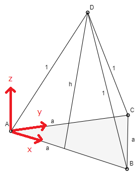
Wie kann ich solche Koordinatenachsen festlegen?
So dass dann z.B. Was der Winkel zwischen der x- und der y-Achse ist? Ja, da bin ich ehrlichgesagt gerade überfragt. Vermutlich nicht einfach 30°. Gibt es da einen bestimmten Standard? \documentclass[margin=5pt, tikz]{standalone} \usepackage{tikz} \usetikzlibrary{calc} \begin{document} \begin{tikzpicture}[%scale=0.7, %x={(1,0)}, z={(0,1)}, y={({cos(30)},{sin(30)})}, x={({cos(30)},{-sin(30)})}, ] \begin{scope}[-latex] \foreach \P/\s/\Pos in {(1,0,0)/x/below, (0,1,0)/y/left, (0,0,2)/z/right} \draw[] (0,0,0) -- \P node[\Pos, pos=0.9,inner sep=2pt]{$\s$}; \end{scope} \end{tikzpicture} \end{document} |
|
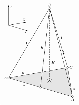
Wie mich @murmeltier aufklärte braucht man eine Definition der Koordinatenachsen vom Typ: \begin{tikzpicture}[..., x={({cos(16.5)*1cm}, {-sin(16.5)*1cm})}, y={({0.9*cos(10)*1cm}, {0.9*sin(10)*1cm})}, z={(0cm,1cm)}, ] Damit \documentclass[margin=5pt, tikz]{standalone} \usepackage{tikz} \usetikzlibrary{calc} \begin{document} \pgfmathsetmacro{\a}{0.85} \pgfmathsetmacro{\m}{\a*sqrt(3)/2} \pgfmathsetmacro{\H}{sqrt(1-\m^2/4)} % Höhe \pgfmathsetmacro{\h}{sqrt(\H^2-\m^2/4)} % Mantellinie \begin{tikzpicture}[scale=5.7, font=\footnotesize, x={({cos(16.5)*1cm}, {-sin(16.5)*1cm})}, y={({0.9*cos(10)*1cm}, {0.9*sin(10)*1cm})}, z={(0cm,1cm)}, ] \coordinate[label=left:$A$] (A) at (0,0,0); \coordinate[label=below:$B$] (B) at (\a,0,0); \coordinate[label=right:$C$] (C) at (0,\a,0); %\coordinate[label=below:$D$] (D) at (0,0,\a); \draw[fill=lightgray!50] (A) -- (B) -- (C) --cycle; \path[] (A) -- (B) node[below, near start]{$a$}; \path[] (B) -- (C) node[right, near start]{$a$}; \path[] (A) -- (C) node[above, near start]{$a$}; \path[] (A) -- ($(B)!0.5!(C)$) coordinate(Ha); \path[] (B) -- ($(A)!0.5!(C)$) coordinate(Hb); \coordinate[] (M) at (intersection of A--Ha and B--Hb); \pgfmathsetmacro{\k}{0.05*\m} \draw[] ($(M)!-\k cm!(C)$) -- ($(M)!\k cm!(C)$); \draw[] ($(M)!-\k cm!(B)$) -- ($(M)!\k cm!(B)$); \path[] (M) --+ (0,0,\H) coordinate[label=$S$] (S); \draw[] (A) -- (S) node[midway, left]{$1$}; \draw[] (B) -- (S) node[midway, right]{$1$}; \draw[] (C) -- (S) node[midway, right]{$1$}; \draw[densely dashed] (S) -- (M) node[near end, right]{$H$}; \draw[] (S) -- ($(A)!0.5!(B)$) node[midway, left]{$h$} coordinate(Mc); \pgfmathsetmacro{\b}{0.3*\a} \begin{scope}[-latex, shift={(0,0,\H-\b)} ] \foreach \P/\s/\Pos in {(\b,0,0)/x/below, (0,\b,0)/y/above, (0,0,\b)/z/right} \draw[] (0,0,0) -- \P node[\Pos, pos=0.9,inner sep=3pt]{$\s$}; \end{scope} % Punkte \foreach \P in {A,B,C,Mc,S} \draw[fill=black!1, scale=1/5.7] (\P) circle (1.75pt); %\node[anchor=north west, align=left, yshift=-1cm, draw] at (A){ %a = \a cm \\ %m = \m cm \\ %H = \H cm \\ %h = \h cm %}; \end{tikzpicture} \end{document} |


für C gilt bei dem dargestellten Koordinatensystem: C(0,k*a,0); normalerweise gelten für ein 3-dim-KOS: - die x1-Achse zeigt mit 225 Grad schräg nach vorne-links; die Einheit ist verkürzt - die x2-Achse zeigt nach rechts - die x3-Achse zeigt nach oben
Das hier scheint ein spezielles KoSy zu sein: Ich habe beim Ausdruck gemessen
AB=12.8cm,AC=12.5cm- vielleicht sollen beide Strecken sogar genau gleich lang sein.Für den Winkel zwischen
ABundACmesse ich grob26.5°, was vermutlich nicht exakt ist.Selbst dann wäre C(a,a,0) falsch! C liegt bei deiner Zeichnung auf der y-Achse, d.h. die x- und die z-Koordinaten sind dann 0. Ein bisselle sollte es schon mathematisch stimmen.
Ja, das war dann ein Denkfehler von mir. In meiner Lösung habe ich es ja richtig.