|
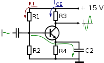
Hallo! Schwierige Frage, ich will versuchen zu beschreiben, worum es mir geht: ·Auf TeXamples finde ich ein Bsp. für einen Transistor, allerdings wurde dieser mittels des Paktes tikzcircuits realisiert. Ich würde gerne mit der TikZ-Lib circuits.ee.IEC arbeiten, da bereits andere Schaltungsteile damit realisiert wurden. ·Nun baue ich bei TikZ-Lib circuits Schaltungen üblicherweise in eine Matrix aus der Lib matrix. Wollte man jetzt darin einen Transistor haben, so müßte der praktisch mit 3 Matrixkoordinaten korrespondieren (da bin ich überfragt, ob sowas übh. geht). ·Dann noch ein Grundproblem, der Transistor bei TeXamples (siehe Link oben) ist nicht 'schön', ich hätte gerne einen Transitor (pnp bzw. npn) wie in folgendem Bild, das man auf dieser wikipedia-Seite findet.
Hat jmd. vll. eine Idee für dieses Problem? Danke fürs Lesen und das Interesse! |
|
Hallo! Für mich ist das ein wenig die Grundsatzfrage, ob man sich jetzt notdürftig bzw. umständlich einen Transistor (oder Ähnliches) selbst zeichnen sollte oder ob der Transistor in absehbarer Zeit in der Lib circuits.ee.IEC zu finden sein wird. Weiß jmd. etwas darüber? Unschöne Lösung \documentclass[margin=5mm,tikz]{standalone} \usepackage{tikz} \begin{document} \begin{tikzpicture}[] %Transistor \draw[very thick, -|] (0,0) -- (2,0); \draw[] (2,0) circle (4mm); \draw[very thick] (2,0) -- (3,1) (2,0) -- (3,-1); \end{tikzpicture} \end{document} |
|
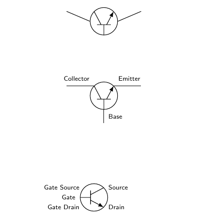
Auf der pgf-users mailing-Liste hatte Carsten Scholtes einmal diesen Ansatz gepostet: \documentclass{article} \usepackage{tikz} \usetikzlibrary{circuits.ee.IEC} %circuits,circuits.logic.US,circuits.logic.IEC}%circuits.ee,circuits.ee.US,} \makeatletter % from pgflibraryshapes.gates.ee.code.tex \pgfdeclareshape{transistor ee} { \inheritsavedanchors[from=circle] \inheritanchorborder[from=circle] \inheritanchor[from=circle]{north} \inheritanchor[from=circle]{north west} \inheritanchor[from=circle]{north east} %\inheritanchor[from=circle]{center} \inheritanchor[from=circle]{west} \inheritanchor[from=circle]{east} \inheritanchor[from=circle]{mid} \inheritanchor[from=circle]{mid west} \inheritanchor[from=circle]{mid east} \inheritanchor[from=circle]{base} \inheritanchor[from=circle]{base west} \inheritanchor[from=circle]{base east} \inheritanchor[from=circle]{south} \inheritanchor[from=circle]{south west} \inheritanchor[from=circle]{south east} \inheritbackgroundpath[from=circle] % New: \anchor{center}{\pgfpointpolar{45}{\radius} \pgf@x=0pt} %why use \centerpoint (0,0), at all? As in: \anchor{center}{\pgfpointpolar{45}{\radius} \pgf@ya=\pgf@y \centerpoint\advance\pgf@y by\pgf@ya} \anchor{base}{\pgfpoint{0pt}{-\radius}} \anchor{collector}{\pgfpointpolar{135}{\radius}} \anchor{emitter}{\pgfpointpolar{45}{\radius}} \anchor{gate}{\pgfpoint{0pt}{-\radius}} \anchor{gate source}{\pgfpointpolar{225}{\radius}} \anchor{gate drain}{\pgfpointpolar{315}{\radius}} \anchor{source}{\pgfpointpolar{135}{\radius}} \anchor{drain}{\pgfpointpolar{45}{\radius}} \anchor{input}{\pgfpointpolar{135}{\radius}} \anchor{output}{\pgfpointpolar{45}{\radius}} % how to use following for drawing inner parts? \anchor{inner base}{\pgfpoint{0pt}{-0.25pt}} \anchor{inner collector}{\pgfpoint{-0.2pt}{-0.25pt}} \anchor{inner emitter}{\pgfpoint{0.2pt}{-0.25pt}} } % from pgflibraryshapes.gates.ee.IEC.code.tex \pgfdeclareshape{generic transistor IEC} { % This shape is a generic circle, to which you can add something to % the before background path using the key % /pgf/generic transistor IEC/before background % When this key is invoked, the transformation matrix will have been % setup such that the circle's center is at the origin and that the % position \pgfpoint{1pt}{0pt} lies exactly on the top of the circle % (and, there, on the middle of the line). \inheritsavedanchors[from=transistor ee] \inheritanchorborder[from=transistor ee] \inheritanchor[from=transistor ee]{north} \inheritanchor[from=transistor ee]{north west} \inheritanchor[from=transistor ee]{north east} \inheritanchor[from=transistor ee]{center} \inheritanchor[from=transistor ee]{west} \inheritanchor[from=transistor ee]{east} \inheritanchor[from=transistor ee]{south} \inheritanchor[from=transistor ee]{south west} \inheritanchor[from=transistor ee]{south east} \inheritanchor[from=transistor ee]{input} \inheritanchor[from=transistor ee]{output} \inheritanchor[from=transistor ee]{base} \inheritanchor[from=transistor ee]{collector} \inheritanchor[from=transistor ee]{emitter} \inheritanchor[from=transistor ee]{gate} \inheritanchor[from=transistor ee]{gate source} \inheritanchor[from=transistor ee]{gate drain} \inheritanchor[from=transistor ee]{source} \inheritanchor[from=transistor ee]{drain} \inheritanchor[from=transistor ee]{inner base} \inheritanchor[from=transistor ee]{inner collector} \inheritanchor[from=transistor ee]{inner emitter} \inheritbackgroundpath[from=transistor ee] \beforebackgroundpath{ { \centerpoint% \pgf@xc=\pgf@x% \pgf@yc=\pgf@y% \pgftransformshift{} \pgfutil@tempdima=\radius% \pgfmathsetlength{\pgf@xb}{\pgfkeysvalueof{/pgf/outer xsep}}% \pgfmathsetlength{\pgf@yb}{\pgfkeysvalueof{/pgf/outer ysep}}% \ifdim\pgf@xb<\pgf@yb% \advance\pgfutil@tempdima by-\pgf@yb% \else% \advance\pgfutil@tempdima by-\pgf@xb% \fi% \pgftransformscale{\pgf@sys@tonumber{\pgfutil@tempdima}} \pgfkeysvalueof{/pgf/generic transistor IEC/before background} } } } % from pgflibraryshapes.gates.ee.IEC.code.tex \pgfkeys{ /pgf/generic transistor IEC/before background/.initial=, } % from tikzlibrarycircuits.ee.code.tex \tikzset{ circuit declare symbol = transistor, } % from top of tikzlibrarycircuits.ee.IEC.code.tex \tikzset{ circuit ee IEC/.append style= { set transistor graphic = transistor IEC graphic,% really IEC? } } % from bulb IEC graphic in tikzlibrarycircuits.ee.IEC.code.tex \tikzset{ transistor IEC graphic/.style={ circuit symbol lines, circuit symbol size=width 3 height 3, shape=generic transistor IEC, /pgf/generic transistor IEC/before background={ \pgfpathmoveto{\pgfpoint{-0.5pt}{-0.25pt}} % inner line \pgfpathlineto{\pgfpoint{0.5pt}{-0.25pt}} \pgfpathmoveto{\pgfpoint{-0.2pt}{-0.25pt}} % to collector \pgfpathlineto{\pgfpointpolar{135}{1pt}} \pgfpathmoveto{\pgfpoint{0pt}{-0.25pt}} % to base \pgfpathlineto{\pgfpoint{0pt}{-1pt}} \pgfusepathqstroke \pgfsetarrowsend{latex} \pgfpathmoveto{\pgfpoint{0.2pt}{-0.25pt}} % to emitter (with arrow) \pgfpathlineto{\pgfpointpolar{45}{1pt}} \pgfusepath{stroke} \pgfsetarrowsend{} }, transform shape } } \makeatother \begin{document} %%%%%%%%%%%%%%%%%%%%%%%%%%%%%%%%%%%%%%%%%%%%%%% \begin{tikzpicture}[scale=1,circuit ee IEC,every node/.style={font=\sffamily\tiny}] %\tikzset{circuit declare symbol=transistor} % possible to specify new anchors? %\tikzset{set transistor graphic=transistor IEC graphic} \draw (0,2) to [transistor] (2,2); \node[transistor,point right] (T1) at (1,0) {}; % to path doesn't connect to input and output anchors... \draw (0,0) -- (T1.input) (T1.output) -- (2,0) (T1.base) -- (1,-1) (T1.base) node[below right]{Base} (T1.collector) node[above left]{Collector} (T1.emitter) node[above right]{Emitter}; \node[transistor,point down] (T2) at (1,-3) {}; % how to reuse most of bipolar for FET graphic? \draw (0,0) -- (T1.input) (T1.output) -- (2,0) (T1.base) -- (1,-1) (T2.gate) node[left]{Gate} (T2.gate source) node[left]{Gate Source} (T2.gate drain) node[left]{Gate Drain} (T2.source) node[right]{Source} (T2.drain) node[right]{Drain}; \end{tikzpicture} \end{document} Ausgabe - ich habe lediglich die Schriftart geändert auf serifenlos und kleiner:
Was kompliziert und lang aussieht, kann man ja einfach in eine Datei auslagern. Poaah, damit hätte ich fast rechnen sollen. Das solltest unbedingt den Machern TikZ-Lib circuits zukommen lassen, so daß man es vll. als einfachen Befehl aufnehmen kann. Es hat mich eh gewundert, weil ich im Handbuch TikZ 3.0.0 gar keine Transistoren finde (es gäbe ja da noch viel: MOSFET, BiFET, SFET usw.). Jetzt hätte ich noch eine Frage, weil ich eine ganze Weile brauchen werde, das alles nachzuvollziehen: Ist es möglich die beiden Striche Source und Drain auf den selben Punkt im Gate zusammenzurücken, so wie im Bild im Startpost?
(29 Mär '14, 23:40)
cis
Da ich inzw. ein paar Erfahrungen dazu sammeln konnte, kann ich das etwas besser überschauen. Der Bild selbst, d.h. die pgf-Figur, ist nicht das Problem, das ist zur Not in 5 Zeilen getan. Knackpunkt ist wohl die Programmierung der üblichen Ansteuerung für 3- oder mehrpolige Bauteile mit "NAME.input1" o.ä., und das macht daraus 2 Seiten Code. Es bleibt also zu Hoffen, das die Transistoren einmal in circuits.ee.IEC aufgenommen werden.
(11 Apr '14, 00:35)
cis
|


