|
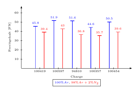
1) Wie kann ich die Legende mittig unter dem X-label platzieren? 2) Wie kann ich einen horizontalen Abstand zwischen den Legendeneinträgen einfügen? 3) Was muss ich statt "stealth" eingeben um als Achsenende einen kleinen vertikalen Strich nach links für die y-Achse und nach unten für die x-Achse zu erhalten Hier mein Minimalbeispiel \documentclass{article} \usepackage{pgfplots} \usepackage{tikz} \usetikzlibrary{arrows,decorations.pathmorphing,backgrounds,positioning,fit,petri,shapes} \begin{figure}[h] \centering \begin{tikzpicture} \begin{axis}[ /pgf/number format/.cd, use comma,1000 sep={}, ybar=10pt,height=8cm,width=12cm, ymin=0, enlargelimits=0.15, enlarge y limits=false, axis lines*=left, axis line style={-stealth}, enlarge y limits={upper,value=0.22}, legend style={at={(1,1), anchor=south east},anchor=south,legend columns=-1}, ylabel={Ferritgehalt [FN]}, xlabel={Charge}, every axis x label/.style={at={(current axis.south)},below=8mm}, symbolic x coords={100419,100597,94810,100357,100454}, xtick=data, nodes near coords, nodes near coords align={vertical}, every node near coord/.append style={anchor=mid west,rotate=60} ] \addplot coordinates {(100419,45.8) (100597,51.9) (94810,51.6) (100357,44.6) (100454,50.5) }; \addplot coordinates {(100419,39.4) (100597,43) (94810,36.8) (100357,35.7) (100454,39.6) }; \legend{$100\%Ar$, $98\%Ar+2\%N_2$} \end{axis} \end{tikzpicture} \caption{Ferritmessung in Abhängigkeit von Charge und Schutzgas}% \label{fig:ferritmessung}% \end{figure} \end{document} |
|
Die Legende mittig unter der dem x-Label positionieren kannst du mit legend style={ at={(current bounding box.south-|current axis.south)}, anchor=north, legend columns=-1 }, Den Abstand nach einem Legendeneintrag kannst du zum Bespiel mit \legend{$100\%Ar$\hspace*{1em}, $98\%Ar+2\%N_2$} Für die gewünschten Achsenenden lädst du am besten die y axis line style={-Bar[left]}, x axis line style={-Bar[right]}, \documentclass{article} \usepackage[utf8]{inputenc} \usepackage{pgfplots} \pgfplotsset{compat=newest} \usetikzlibrary{arrows.meta} \begin{document} \begin{figure}[h] \centering \begin{tikzpicture} \begin{axis}[ /pgf/number format/.cd, use comma,1000 sep={}, ybar=10pt,height=8cm,width=12cm, ymin=0, enlarge x limits=0.15, enlarge y limits={upper,value=0.22}, axis lines*=left, y axis line style={-Bar[left]}, x axis line style={-Bar[right]}, legend style={ at={(current bounding box.south-|current axis.south)}, anchor=north, legend columns=-1 }, ylabel={Ferritgehalt [FN]}, xlabel={Charge}, every axis x label/.style={at={(current axis.south)},below=8mm}, symbolic x coords={100419,100597,94810,100357,100454}, xtick=data, nodes near coords, nodes near coords align={vertical}, every node near coord/.append style={anchor=mid west,rotate=60} ] \addplot coordinates {(100419,45.8) (100597,51.9) (94810,51.6) (100357,44.6) (100454,50.5) }; \addplot coordinates {(100419,39.4) (100597,43) (94810,36.8) (100357,35.7) (100454,39.6) }; \legend{$100\%Ar$\hspace*{1em}, $98\%Ar+2\%N_2$} \end{axis} \end{tikzpicture} \caption{Ferritmessung in Abhängigkeit von Charge und Schutzgas}% \label{fig:ferritmessung}% \end{figure} \end{document} Wie war das, man soll kein Office- (Excel-)Design nachtexen? :P [OK, könnter löschen...]
(25 Apr '14, 21:12)
cis
Alternativ Vorschlag? Das ist ein normales Histogramm... Excel nutzt das auch, ja =)
(25 Apr '14, 23:12)
wiewowas
|
|
Das mit dem "Excel-Design" sollte keine Kritik sein. pgfplots scheint sich hier (leider hätte ich fast gesagt), in den Formatvorlagen, am Office-Design zu orientieren. Was den Stil anbelangt, orientiere ich mich i.d.R. daran, wie man das von Hand zeichnen würde. Das folgende Bild bekommt man vermutlich auch mit pgfplots hin, da ich mich da aber weniger auskenne, auf die Schnelle eine TikZ-Umsetzung. (TikZ hat vll. irgendwo den Vorteil, daß es keinerlei Stile vorgibt, will man welche haben, muß man sie alle selbst einstellen.)
\documentclass[margin=5mm]{standalone} \usepackage[ngerman]{babel} \usepackage{tikz} \usepackage{amsmath, amssymb} %=========== \begin{document} %=========== \begin{tikzpicture}[ x=1.5cm, y=0.075cm, scale=0.75, font=\tiny, >=latex, %Voreinstellung für Pfeilspitzen ] % x-Achse \draw[->] (0,0) -- (6,0) node[midway, yshift=-1.5em] {Charge}; %Zahlen auf x-Achse \foreach \x in {1,...,5}{% \draw[shift={(\x,0)},color=black] (0pt,2pt) -- (0pt,-2pt) node[below] {$$}; \coordinate[xshift=-0.75em] (\x-L) at (\x,0); \coordinate (\x-M) at (\x,0); \coordinate[xshift=0.75em] (\x-R) at (\x,0); }% %X-Werte \node[below] at (1-M) {100419}; \node[below] at (2-M) {100597}; \node[below] at (3-M) {94810}; \node[below] at (4-M) {100357}; \node[below] at (5-M) {100454}; % y-Achse \draw[->] (0,0) -- (0,67.5) node[midway, rotate=90, yshift=2em] {Ferritgehalt [FN]};%node[above left] %Zahlen auf y-Achse \foreach \y in {10,20,...,60} \draw[shift={(0,\y)},color=black] (2pt,0pt) -- (-2pt,0pt) node[left] {$\y$}; %Messwerte - Links \node[xshift=-0.75em, above, blue] (y-1-L) at (1,45.8){45.8}; \node[xshift=-0.75em, above, blue] (y-2-L) at (2,51.9){51.9}; \node[xshift=-0.75em, above, blue] (y-3-L) at (3,51.6){51.6}; \node[xshift=-0.75em, above, blue] (y-4-L) at (4,44.6){44.6}; \node[xshift=-0.75em, above, blue] (y-5-L) at (5,50.5){50.5}; \foreach \i in {1,...,5} \draw[blue, thick, -|] (\i-L) -- (y-\i-L); %Messwerte - Rechts \node[xshift=0.75em, above, red] (y-1-R) at (1,39.4){39.4}; \node[xshift=0.75em, above, red] (y-2-R) at (2,43){43}; \node[xshift=0.75em, above, red] (y-3-R) at (3,36.8){36.8}; \node[xshift=0.75em, above, red] (y-4-R) at (4,35.7){35.7}; \node[xshift=0.75em, above, red] (y-5-R) at (5,39.6){39.6}; \foreach \i in {1,...,5} \draw[red, thick, -|] (\i-R) -- (y-\i-R); %Legende: \draw[draw=none] (0,0) -- (6,0) node[draw, midway, yshift=-2.5em] {\textcolor{blue}{$100\%Ar$}, \textcolor{red}{$98\%Ar+2\%N_2$}}; \end{tikzpicture} %=========== \end{document} %=========== |

