|
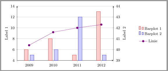
Um in einem Diagramm zwei verschiedene y-Achsen verwenden zu können, habe ich zwei
In der Legende fällt auf, dass der Abstand zwischen den Zeilen unterschiedlich und die Texteinträge nicht aneinander ausgerichtet sind. Wie kann ich das ändern? Mein bisheriger Code: \documentclass[margin=5pt]{standalone} \usepackage{pgfplots} \pgfplotsset{compat=newest} \begin{document} \begin{tikzpicture}[node font=\footnotesize, farbe/.style={draw=#1!80!black,fill=#1!20}] \pgfplotsset{ height=4cm, width=7cm, scale only axis, xmin=0.5, xmax=4.5, legend style={draw=none,legend cell align=left,} } % Barplots \begin{axis}[ axis x line=bottom, xtick={0.5, 1, 2, 3, 4, 4.5}, xticklabels={,2009, 2010, 2011, 2012, }, axis y line=left, ylabel=Label 1, ymin=4, ymax=14, ytick={4,6,...,14}, ymajorgrids=true, ybar=4pt, bar width=8pt, legend style={name={leg1},at={(1.25,0.65)},anchor=north west}, ] \addplot[farbe=red] plot coordinates {(1, 6) (2, 8) (3, 5) (4, 13)}; \addplot[farbe=blue] plot coordinates {(1, 5) (2, 6) (3, 12) (4, 5)}; \legend{Barplot 1, Barplot 2} \end{axis} % Linie \begin{axis}[ axis x line=none, xtick=\empty, axis y line=right, ylabel=Label 2, ymin=39, ymax=44, ytick={39,...,44}, legend style={at={(leg1.south west)},anchor=north west} ] \addplot[red!50!blue,mark=*] plot coordinates {(01, 40.4) (02, 41.6) (03, 42) (04, 42.3)}; \legend{Linie} \end{axis} \end{tikzpicture} \end{document} |
|
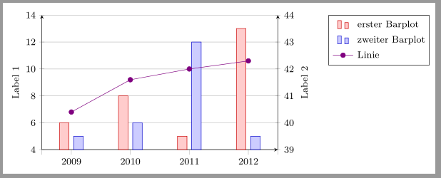
Wenn man hinter die \documentclass[margin=5pt]{standalone} \usepackage{pgfplots} \pgfplotsset{compat=newest} \usetikzlibrary{matrix} \begin{document} \begin{tikzpicture}[node font=\footnotesize, farbe/.style={draw=#1!80!black,fill=#1!20}] \pgfplotsset{ height=4cm, width=7cm, scale only axis, xmin=0.5, xmax=4.5, } % Barplots \begin{axis}[ axis x line=bottom, xtick={0.5, 1, 2, 3, 4, 4.5}, xticklabels={,2009, 2010, 2011, 2012, }, axis y line=left, ylabel=Label 1, ymin=4, ymax=14, ytick={4,6,...,14}, ymajorgrids=true, ybar=4pt, bar width=8pt ] \addplot[farbe=red] plot coordinates {(1, 6) (2, 8) (3, 5) (4, 13)}; \label{pgfplots:plot1} \addplot[farbe=blue] plot coordinates {(1, 5) (2, 6) (3, 12) (4, 5)}; \label{pgfplots:plot2} \end{axis} % Linie \begin{axis}[ axis x line=none, xtick=\empty, axis y line=right, ylabel=Label 2, ymin=39, ymax=44, ytick={39,...,44}, ] \addplot[red!50!blue,mark=*] plot coordinates {(01, 40.4) (02, 41.6) (03, 42) (04, 42.3)}; \label{pgfplots:plot3} \end{axis} % Legende \matrix[ matrix of nodes, anchor=north west, draw,% Rahmen um Legende inner sep=0.2em, column 1/.style={nodes={anchor=center}}, column 2/.style={nodes={anchor=west},font=\strut}, draw ] at([xshift=1.5cm]current axis.north east){ \ref{pgfplots:plot1}& erster Barplot\\ \ref{pgfplots:plot2}& zweiter Barplot\\ \ref{pgfplots:plot3}& Linie\\}; \end{tikzpicture} \end{document} Ergebnis nach zwei Durchläufen (wegen der Referenzen):
|


Die Frage ist zum Archivieren gedacht, kein Support benötigt. Sie stammt ursprünglich von golatex. Ich habe zwar selbst auch geantwortet, aber alternative Antworten sind sehr willkommen!