|
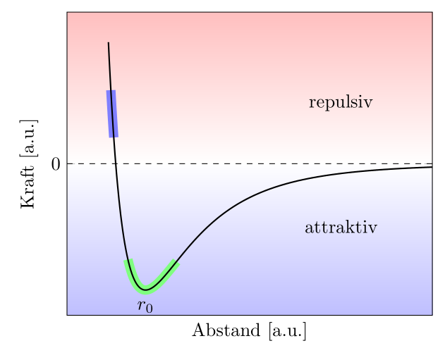
Hallo Leute! Ich hab ein kleines Problem in einer TikZ-Zeichnung, die mE durch einen numerischen Fehler erklärbar wäre. Hier der Quelltext: \documentclass[tikz,border=3mm]{standalone} \usepackage{pgfplots} \begin{document} \begin{tikzpicture} \begin{axis}[domain = 0.97:2.3, samples=400, xmin = 0.8, xmax = 2.3, ymin = -0.3, ymax = 0.3, ytick = \empty, xtick = \empty, xlabel = {Abstand [a.u.]}, ylabel = {Kraft [a.u.]}, extra y ticks = {0}, xlabel near ticks, ylabel near ticks, set layers,] \begin{pgfonlayer}{axis background} \fill[shade, top color=blue!0, bottom color=blue!25] (rel axis cs:0,0)--(rel axis cs:1,0)-- (rel axis cs:1,0.5)--(rel axis cs:0,0.5)--cycle; \fill[shade, top color=red!25, bottom color=red!0] (rel axis cs:0,0.5)--(rel axis cs:1,0.5)-- (rel axis cs:1,1)--(rel axis cs:0,1)--cycle; \end{pgfonlayer} \addplot[line width=5pt,color = green!50, domain = 1.05:1.25] {1/x^12-1/x^6}; \addplot[line width=5pt,color = blue!50, domain = 0.98:0.992] {1/x^12-1/x^6}; \addplot[thick] {1/x^12-1/x^6}; \node[anchor= north] at (axis cs: 1.122462048,-0.26) {$r_0$}; \draw[dashed,thin] (axis cs: 0.8, 0 )-- (axis cs: 2.3, 0); \node[anchor = north] at (rel axis cs:0.75,0.75) {repulsiv}; \node[anchor = south] at (rel axis cs:0.75,0.25) {attraktiv}; \end{axis} \end{tikzpicture} \end{document} Wie ihr seht, ist der blaue Bereich auf der Kurve nicht durch vier, sondern durch fünf Ecken begrenzt. Ich nehme an, dass dies an dem extremen Anstieg an der Kurve in dem Bereich liegt. Hat jemand ne Idee, wie man das Beispiel so abändern kann, dass die Markierung so aussieht, wie die Grüne unten, also ordentlich? Vielen Dank schonmal! |
|
Das Problem kommt von der hohen Anzahl der Verwende
Code: \documentclass[tikz,border=3mm]{standalone} \usepackage{pgfplots} \pgfplotsset{compat=1.11} \begin{document} \begin{tikzpicture} \begin{axis}[domain = 0.97:2.3, samples=100,% <- nur 100 statt 400 xmin = 0.8, xmax = 2.3, ymin = -0.3, ymax = 0.3, ytick = \empty, xtick = \empty, xlabel = {Abstand [a.u.]}, ylabel = {Kraft [a.u.]}, extra y ticks = {0}, xlabel near ticks, ylabel near ticks, set layers,] \begin{pgfonlayer}{axis background} \fill[shade, top color=blue!0, bottom color=blue!25] (rel axis cs:0,0)--(rel axis cs:1,0)-- (rel axis cs:1,0.5)--(rel axis cs:0,0.5)--cycle; \fill[shade, top color=red!25, bottom color=red!0] (rel axis cs:0,0.5)--(rel axis cs:1,0.5)-- (rel axis cs:1,1)--(rel axis cs:0,1)--cycle; \end{pgfonlayer} \addplot[line width=5pt,color = green!50, domain = 1.05:1.25] {1/x^12-1/x^6}; \addplot[line width=5pt,color = blue!50, domain = 0.98:0.992] {1/x^12-1/x^6}; \addplot[thick, samples=400% 400 für die Gesamtkurve ] {1/x^12-1/x^6}; \node[anchor= north] at (axis cs: 1.122462048,-0.26) {$r_0$}; \draw[dashed,thin] (axis cs: 0.8, 0 )-- (axis cs: 2.3, 0); \node[anchor = north] at (rel axis cs:0.75,0.75) {repulsiv}; \node[anchor = south] at (rel axis cs:0.75,0.25) {attraktiv}; \end{axis} \end{tikzpicture} \end{document} danke! :-)
(23 Okt '14, 16:47)
lorbj
|


Also man kann das Problem umgehen, indem man die Grenzen geschickt wählt, so sieht es bei ´domain = 0.98:0.995´ ganz vernünftig aus, aber das ist ja eigentlich keine richtige Lösung.