|
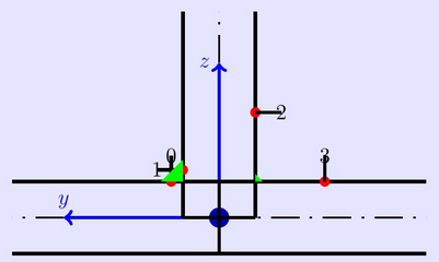
Hallo; Mich würde es interessieren wie man die schwarze Umrandung von den von mir gezeichneten Kreisen (die mit der Farbe rot gefüllt sind) ausblendet sodas ich nur einen roten Punkt habe ohne schwarzen Umrandungskreis. Gleiches gilt auch für meinen Polygonzug (grünes Dreieck). Danke. \documentclass[12pt]{article} \usepackage{tikz} \begin{document} \begin{tikzpicture} \node[anchor=south west,inner sep=0](Bild)at(0,0){\color{blue!10}\rule{20cm}{20cm}}; \begin{scope}[ xshift=5cm,yshift=8cm, opacity=1, description/.style={ fill=green, fill opacity=1, text opacity=1 } ] %\draw[step=1,red,thin] (-7,-7) grid (7,7); %Hier habe ich den Zeichen-Bereich der \node[circle,fill=blue!70!black] at (0,0){};% Ursprung des Gitters (Nur als Hilfe) \begin{scope}[line width=2pt] \draw[dash pattern=on 5.5mm off 2mm on .5mm off 2mm, -,line width=1pt]( 0,0)--(-4,0); \draw[dash pattern=on 5.5mm off 2mm on .5mm off 2mm, -,line width=1pt]( 0,0)--(0,4); \draw[dash pattern=on 5.5mm off 2mm on .5mm off 2mm, -,line width=1pt]( 0,0)--(4,0); \draw[->,blue]( 0,0)--(0,3)node[left]{$z$}; \draw[->,blue]( 0,0)--(-3,0)node[above]{$y$}; \draw(0,-0.7)--(-4,-0.7); \draw(0,-0.7)--(0,0.7); \draw(0,0.7)--(-4,0.7); \draw(-0.7,0)--(-0.7,4); \draw(-0.7,0)--(0.7,0); \draw(0.7,0)--(0.7,4); \draw(0,0.7)--(4,0.7); \draw(0,0.7)--(0,-0.7); \draw(0,-0.7)--(4,-0.7); \draw[fill=red] (-0.9243,0.7)circle (0.1cm); \draw[fill=red] (-0.7,0.9243)circle (0.1cm); \draw[fill=red] (0.7,2.0414)circle (0.1cm); \draw[fill=red] (2.0414,0.7)circle (0.1cm); \draw(-0.9243,0.7)--(-0.9243,1.2); \node[rotate=0] at (-0.9243,1.2){0}; \draw(-0.7,0.9243)--(-1.2,0.9243); \node[rotate=0] at (-1.2,0.9243){1}; \draw(0.7,2.0414)--(1.2,2.0414); \node[rotate=0] at (1.2,2.0414){2}; \draw(2.0414,0.7)--(2.0414,1.2); \node[rotate=0] at (2.0414,1.2){3}; \draw[fill=green](-0.7,0.7)--(-1.1243,0.7)--(-0.7,0.7)--(-0.7,1.1243)--(-0.7,1.1243)--(-1.1243,0.7); \draw[fill=green](0.7,0.7)--(0.8414,0.7)--(0.7,0.7)--(0.7,0.8414)--(0.7,0.8414)--(0.8414,0.7); \end{scope} \end{scope} \end{tikzpicture} \end{document} |
|
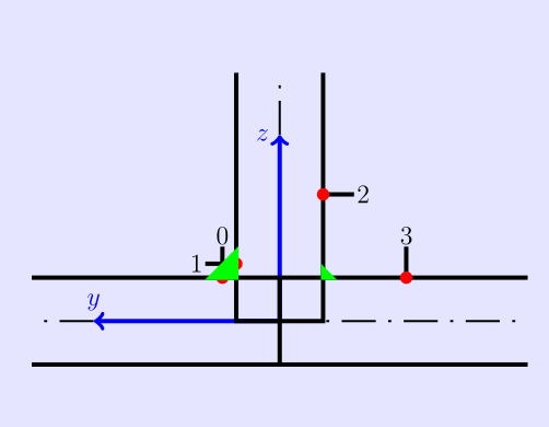
Wenn ich richtig verstanden habe, was Du willst, dann musst Du einfach \documentclass[12pt]{article} \usepackage{tikz} \begin{document} \begin{tikzpicture} \node[anchor=south west,inner sep=0](Bild)at(0,0){\color{blue!10}\rule{20cm}{20cm}}; \begin{scope}[ xshift=5cm,yshift=8cm, opacity=1, description/.style={ fill=green, fill opacity=1, text opacity=1 } ] %\draw[step=1,red,thin] (-7,-7) grid (7,7); %Hier habe ich den Zeichen-Bereich der \node[circle,fill=blue!70!black] at (0,0){};% Ursprung des Gitters (Nur als Hilfe) \begin{scope}[line width=2pt] \draw[dash pattern=on 5.5mm off 2mm on .5mm off 2mm, -,line width=1pt]( 0,0)--(-4,0); \draw[dash pattern=on 5.5mm off 2mm on .5mm off 2mm, -,line width=1pt]( 0,0)--(0,4); \draw[dash pattern=on 5.5mm off 2mm on .5mm off 2mm, -,line width=1pt]( 0,0)--(4,0); \draw[->,blue]( 0,0)--(0,3)node[left]{$z$}; \draw[->,blue]( 0,0)--(-3,0)node[above]{$y$}; \draw(0,-0.7)--(-4,-0.7); \draw(0,-0.7)--(0,0.7); \draw(0,0.7)--(-4,0.7); \draw(-0.7,0)--(-0.7,4); \draw(-0.7,0)--(0.7,0); \draw(0.7,0)--(0.7,4); \draw(0,0.7)--(4,0.7); \draw(0,0.7)--(0,-0.7); \draw(0,-0.7)--(4,-0.7); \fill[red] (-0.9243,0.7)circle (0.1cm); \fill[red] (-0.7,0.9243)circle (0.1cm); \fill[red] (0.7,2.0414)circle (0.1cm); \fill[red] (2.0414,0.7)circle (0.1cm); \draw(-0.9243,0.7)--(-0.9243,1.2); \node[rotate=0] at (-0.9243,1.2){0}; \draw(-0.7,0.9243)--(-1.2,0.9243); \node[rotate=0] at (-1.2,0.9243){1}; \draw(0.7,2.0414)--(1.2,2.0414); \node[rotate=0] at (1.2,2.0414){2}; \draw(2.0414,0.7)--(2.0414,1.2); \node[rotate=0] at (2.0414,1.2){3}; \fill[green](-0.7,0.7)--(-1.1243,0.7)--(-0.7,0.7)--(-0.7,1.1243)--(-0.7,1.1243)--(-1.1243,0.7); \fill[green](0.7,0.7)--(0.8414,0.7)--(0.7,0.7)--(0.7,0.8414)--(0.7,0.8414)--(0.8414,0.7); \end{scope} \end{scope} \end{tikzpicture} \end{document}
Optimal ist das aber noch nicht. Ich habe nur die Kreise und Polygone ohne Rand gezeichnet. Tatsächlich würde ich die Ziffern-Nodes noch etwas weiter von den Linien abrücken. Aber das war je nicht die Frage. @saputello das mit den ziffern habe ich schon erledigt. Danke
(30 Jun '15, 14:04)
basel
|
|
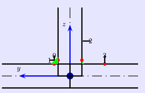
@saputello hat die Frage ja schon beantwortet: wenn Du keine schwarzen Striche als Rand für die Elemente haben möchtest, musst Du entweder auf das Zeichnen der Linien verzichten ( In jedem Fall würde ich aber Stile für die einzelnen Elemente definieren und die Anzahl der eingetippten Koordinatenangaben verringern, zumal die recht kompliziert aussehen. \documentclass[12pt]{article} \usepackage{tikz} \begin{document} \begin{center} \begin{tikzpicture}[ strichpunkt/.style={dash pattern=on 5.5mm off 2mm on .5mm off 2mm, -,line width=1pt}, achse/.style={->,blue}, punkt/.style={circle,fill,red,inner sep=0pt,minimum size=.2cm}, dreieck/.style={fill,draw,green}, nummer/.style={inner sep=.2pt} ] \node[anchor=south west,inner sep=0](Bild){\color{blue!10}\rule{20cm}{20cm}}; \begin{scope}[xshift=5cm,yshift=8cm,line width=2pt] %\draw[step=1,red,thin] (-7,-7) grid (7,7); %Hier habe ich den Zeichen-Bereich der %\node[circle,fill=blue!70!black]{};% Ursprung des Gitters (Nur als Hilfe) \draw[strichpunkt] (0,0)--(-4,0) (0,0)--(0,4) (0,0)--(4,0) ; \draw[achse]( 0,0)--(0,3)node[left]{$z$}; \draw[achse]( 0,0)--(-3,0)node[above]{$y$}; \draw (-4,-0.7)--(4,-0.7) (-4,0.7)--(4,0.7) (0,-0.7)--(0,0.7) (-0.7,4)--(-0.7,0)--(0.7,0)--(0.7,4) ; \draw(-0.9243,0.7)coordinate(p1)--+(0,.5)node[nummer,above]{0}; \draw(-0.7,0.9243)coordinate(p2)--+(-.5,0)node[nummer,left]{1}; \draw(0.7,2.0414)coordinate(p3)--+(.5,0)node[nummer,right]{2}; \draw(2.0414,0.7)coordinate(p4)--+(0,.5)node[nummer,above]{3}; \foreach \i in {1,...,4}\node[punkt] at (p\i){}; \path[dreieck] (-0.7,0.7)--(-1.1243,0.7)--(-0.7,1.1243)--cycle (0.7,0.7)--(0.8414,0.7)--(0.7,0.8414)--cycle ; \end{scope} \end{tikzpicture} \end{center} \end{document}
Die Punkte habe ich jetzt über den Strichen eingefügt. Kann sein, dass Du auch die gefüllten Dreiecke lieber unter den Strichen haben möchtest. |
|
Eine ALternative mit PSTricks. Mit \documentclass[12pt,a4paper]{article} \usepackage{pst-node} \begin{document} \begin{pspicture}(20,20) \psframe*[linecolor=blue!10](20,20) \rput(5,8){% \pscircle*[linecolor=blue!70!black]{2mm} \psset{linewidth=2pt,dash=5.5mm 2mm .5mm 2mm,shortput=nab,arrowscale=1.5} \psline[linestyle=dashed,linewidth=1pt](-4,0)(4,0) \psline[linestyle=dashed,linewidth=1pt](0,0)(0,4) \pcline[linecolor=blue]{->}(0,0)(0,3)^[npos=1]{$z$} \pcline[linecolor=blue]{->}(0,0)(-3,0)_[npos=1]{$y$} \psline(-4,-0.7)(4,-0.7) \psline(-4,0.7)(4,0.7) \psline(0,-0.7)(0,0.7) \psline(-0.7,4)(-0.7,0)(0.7,0)(0.7,4) \pscircle*[linecolor=red](-0.9243,0.7){1mm} \pscircle*[linecolor=red](-0.7,0.9234){1mm} \pscircle*[linecolor=red](0.7,0.9243){1mm} \pscircle*[linecolor=red](2.0414,0.7){1mm} \pcline[nodesepA=0.5mm](-0.9243,0.7)(-0.9243,1.2)\ncput[npos=1]{0} \pcline[nodesepA=0.5mm](-0.7,0.9243)(-1.2,0.9243)\ncput[npos=1]{1} \pcline[nodesepA=0.5mm](0.7,2.0414)(1.2,2.0414)\ncput[npos=1]{2} \pcline[nodesepA=0.5mm](2.0414,0.7)(2.0414,1.2)\ncput[npos=1]{3} \pspolygon*[linecolor=green](-1.1243,0.7)(-0.7,0.7)(-0.7,1.1243) \pspolygon*[linecolor=green](0.7,0.7)(0.8414,0.7)(0.7,0.8414) } \end{pspicture} \end{document}
|
|
@danke an alle. Falls jemanden mein einfacher Code interessieren sollte .... -> So habe ich es realisiert: \documentclass[12pt]{article} \usepackage{tikz} \begin{document} \begin{tikzpicture} \node[anchor=south west,inner sep=0](Bild)at(0,0){\color{blue!10}\rule{20cm}{20cm}}; \begin{scope}[ xshift=5cm,yshift=8cm, opacity=1, description/.style={ fill=green, fill opacity=1, text opacity=1 } ] \begin{scope}[line width=1pt] \fill[green](-0.7,0.7)--(-1.1243,0.7)--(-0.7,0.7)--(-0.7,1.1243)--(-0.7,1.1243)--(-1.1243,0.7); \fill[green](0.7,0.7)--(0.8414,0.7)--(0.7,0.7)--(0.7,0.8414)--(0.7,0.8414)--(0.8414,0.7); \draw[dash pattern=on 5.5mm off 2mm on .5mm off 2mm, -,line width=0.5pt]( 0,0)--(-4,0); \draw[dash pattern=on 5.5mm off 2mm on .5mm off 2mm, -,line width=0.5pt]( 0,0)--(0,4); \draw[dash pattern=on 5.5mm off 2mm on .5mm off 2mm, -,line width=0.5pt]( 0,0)--(4,0); \draw(0,-0.7)--(-4,-0.7); \draw(0,-0.7)--(0,0.7); \draw(0,0.7)--(-4,0.7); \draw(-0.7,0)--(-0.7,4); \draw(-0.7,0)--(0.7,0); \draw(0.7,0)--(0.7,4); \draw(0,0.7)--(4,0.7); \draw(0,0.7)--(0,-0.7); \draw(0,-0.7)--(4,-0.7); \fill[red](-0.9243,0.7)circle (0.1cm); \fill[red] (-0.7,0.9243)circle (0.1cm); \fill[red] (0.7,2.0414)circle (0.1cm); \fill[red] (2.0414,0.7)circle (0.1cm); \draw[red](-0.9243,0.7)--(-0.9243,1.2); \node[rotate=0,red] at (-1.1243,1.4){0}; \draw[red](-0.7,0.9243)--(-1.2,0.9243); \node[rotate=0,red] at (-1.4,1.1243){1}; \draw[red](0.7,2.0414)--(1.2,2.0414); \node[rotate=0,red] at (1.4,2.2414){2}; \draw[red](2.0414,0.7)--(2.0414,1.2); \node[rotate=0,red] at (2.2414,1.4){3}; \draw[->,blue,line width=1.5pt]( 0,0)--(0,3)node[left]{$z$}; \draw[->,blue,line width=1.5pt]( 0,0)--(-3,0)node[above]{$y$}; \end{scope} \end{scope} \end{tikzpicture} \end{document} |


