|
[Archiv der Frage Plot to illustrate linear regression von LeO auf TeX.SX] Im Rahmen einer Lehrtätigkeit möchte ich die Grundlagen der linearen Regression erklären und wie sie erweitert werden kann. Da ich kein TeXpert bin, befürchte ich, dass meine Idee vielleicht zu kompliziert und schwieriger ist als gedacht. Ich habe schon viele schöne Skizzen mit TikZ und pgfplots gesehen. Ich habe gesucht und schließlich dieses Bild gefunden: Das Bild sieht sehr passend aus, weil ich daran erklären kann wie lineare Regression aussehen könnte. Aber das Problem ist, dass ich das Bild nicht verändern kann, z.B. ein Gitter zeichnen, die Bezeichnungen wie Möchte mir jemand Hilfestellung anbieten? Es ist auch kein Problem, wenn mich jemand auf existierende Beispiele hinweist. |
|
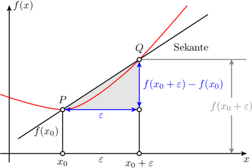
Mit TikZ ist das wirklich leicht. Im folgenden habe ich Plain TeX verwendet, weshalb man Den folgenden Code setzt man mit \input tikz.tex \nopagenumbers% for cropping \usetikzlibrary{arrows,intersections} \tikzpicture[ thick, >=stealth', dot/.style = { draw, fill=white, circle, inner sep=0pt, minimum size=4pt } ] \coordinate (O) at (0,0); \draw[->] (-0.3,0) -- (8,0) coordinate[label={below:$x$}] (xmax); \draw[->] (0,-0.3) -- (0,5) coordinate[label={right:$f(x)$}] (ymax); \path[name path=x] (0.3,0.5) -- (6.7,4.7); \path[name path=y] plot[smooth] coordinates {(-0.3,2) (2,1.5) (4,2.8) (6,5)}; \scope[name intersections={of=x and y,name=i}] \fill[gray!20] (i-1) -- (i-2 |- i-1) -- (i-2) -- cycle; \draw (0.3,0.5) -- (6.7,4.7) node[pos=0.8,below right] {Sekante}; \draw[red] plot[smooth] coordinates {(-0.3,2) (2,1.5) (4,2.8) (6,5)}; \draw (i-1) node[dot,label={above:$P$}] (i-1) {} -- node[left] {$f(x_0)$} (i-1 |- O) node[dot,label={below:$x_0$}] {}; \path (i-2) node[dot,label={above:$Q$}] (i-2) {} -- (i-2 |- i-1) node[dot] (i-12) {}; \draw (i-12) -- (i-12 |- O) node[dot,label={below:$x_0 + \varepsilon$}] {}; \draw[blue,<->] (i-2) -- node[right] {$f(x_0 + \varepsilon) - f(x_0)$} (i-12); \draw[blue,<->] (i-1) -- node[below] {$\varepsilon$} (i-12); \path (i-1 |- O) -- node[below] {$\varepsilon$} (i-2 |- O); \draw[gray] (i-2) -- (i-2 -| xmax); \draw[gray,<->] ([xshift=-0.5cm]i-2 -| xmax) -- node[fill=white] {$f(x_0 + \varepsilon)$} ([xshift=-0.5cm]xmax); \endscope \endtikzpicture \bye Die produziert die folgende Ausgabe (freigestellt) Da die Schnittpunkt mit der Mein Arbeitsablauf zum Erstellen von Animationen ist der folgende:
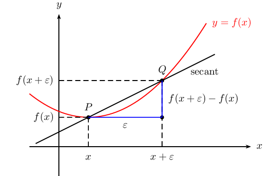
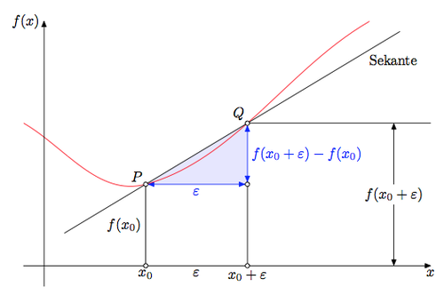
Im folgenden befindet sich der Code zum erstellen der Animation. Ich habe die zusätzlichen und veränderten Zeilen markiert um den Unterschied zum obigen Code hervorzuheben. \input tikz.tex \nopagenumbers% for cropping \usetikzlibrary{arrows,intersections} \foreach \Q in {4,4.1,4.2,...,5,4.9,4.8,...,4.1} {%<-- neu \tikzpicture[ thick, >=stealth', dot/.style = { draw, fill=white, circle, inner sep=0pt, minimum size=4pt } ] \coordinate (O) at (0,0); \draw[->] (-0.3,0) -- (8,0) coordinate[label={below:$x$}] (xmax); \draw[->] (0,-0.3) -- (0,5) coordinate[label={right:$f(x)$}] (ymax); \path[name path=x] (0.3,0.5) -- (6.7,4.7); \path[name path=y] plot[smooth] coordinates {(-0.3,2) (2,1.5) (\Q,2.8) (6,5)};%<-- geändert \scope[name intersections={of=x and y,name=i}] \fill[gray!20] (i-1) -- (i-2 |- i-1) -- (i-2) -- cycle; \draw (0.3,0.5) -- (6.7,4.7) node[pos=0.8,below right] {Sekante}; \draw[red] plot[smooth] coordinates {(-0.3,2) (2,1.5) (\Q,2.8) (6,5)};%<-- geändert \draw (i-1) node[dot,label={above:$P$}] (i-1) {} -- node[left] {$f(x_0)$} (i-1 |- O) node[dot,label={below:$x_0$}] {}; \path (i-2) node[dot,label={above:$Q$}] (i-2) {} -- (i-2 |- i-1) node[dot] (i-12) {}; \draw (i-12) -- (i-12 |- O) node[dot,label={below:$x_0 + \varepsilon$}] {}; \draw[blue,<->] (i-2) -- node[right] {$f(x_0 + \varepsilon) - f(x_0)$} (i-12); \draw[blue,<->] (i-1) -- node[below] {$\varepsilon$} (i-12); \path (i-1 |- O) -- node[below] {$\varepsilon$} (i-2 |- O); \draw[gray] (i-2) -- (i-2 -| xmax); \draw[gray,<->] ([xshift=-0.5cm]i-2 -| xmax) -- node[fill=white] {$f(x_0 + \varepsilon)$} ([xshift=-0.5cm]xmax); \endscope \endtikzpicture \eject%<-- neu }%<-- neu \bye Zum Spaß mit PSTricks vom TeX.SX User der ständig seinen Namen ändert, natürlich auf TeX.SX. \documentclass[pstricks]{standalone} \usepackage{pst-plot,pst-eucl} \def\f(#1){((#1-1)^2+5)/5} \def\L#1#2#3{\psCoordinates[linestyle=dashed](#1)\uput[-90](#1|0,0){$#2\mathstrut$}\uput[180](0,0|#1){$#3$}} \begin{document} \begin{pspicture}[algebraic,saveNodeCoors,NodeCoorPrefix=N](-2,-1)(7,5) \psaxes[labels=none,ticks=none]{->}(0,0)(-1,-1)(6.5,4.5)[$x$,0][$y$,90] \psplot[linecolor=red]{-1}{5}{\f(x)} \pstGeonode[PosAngle=90](*1 {\f(x)}){P}(*3.5 {\f(x)}){Q} \psdot(Q|P) \pcline[nodesep=-2](P)(Q) \L{P}{x}{f(x)} \L{Q}{x+\varepsilon}{f(x+\varepsilon)} \pcline[linecolor=blue](P)(Q|P)\nbput{$\varepsilon$} \pcline[linecolor=blue](Q)(!NQx NPy)\naput{$f(x+\varepsilon)-f(x)$} \uput[-45]([nodesep=-1]{p}Q){secant} \uput[0](*5 {\f(x)}){\textcolor{red}{$y=f(x)$}} \end{pspicture} \end{document} Mit MetaPost und dem Metafun-Format von fpast auf TeX.SX. Das Bild übersetzt man mit input latexmp; setupLaTeXMP(textextlabel=enable, mode=rerun); vardef drawemptydot expr z = save circle; path circle; circle = fullcircle scaled 3bp shifted z; unfill circle; draw circle; enddef; u := cm; % Unit length beginfig(1); xmin := -0.5; xmax := 9.5; ymin := -0.5; ymax := 6; path curve; curve = (-0.5, 3.5){dir -30} .. (2.5, 2){dir 15} .. (5, 3.5) .. (8, 6){dir 30}; % Triangle and labels z.P = point 1 of curve; z.Q = point 2 of curve; z.R = (x.Q, y.P); z.S = (x.P, 0); z.T = (x.Q, 0); fill z.P--z.Q--z.R--cycle scaled u withcolor 0.9[blue, white]; % drawoptions(withcolor blue); drawdblarrow (z.P -- z.R) scaled u shortened 2bp; drawdblarrow (z.R -- z.Q) scaled u shortened 2bp; label.bot("$\varepsilon$", u*.5[z.P, z.R]); label.rt("$f(x_0+\varepsilon) - f(x_0)$", u*.5[z.R, z.Q]); % drawoptions(withcolor black); draw ((x.P, 0) -- z.P) scaled u; draw ((x.Q, 0) -- z.R) scaled u; draw (z.Q -- (xmax, y.Q)) scaled u; % The curve draw curve scaled u withcolor red; % Axes drawarrow (xmin*u, 0) -- (xmax*u, 0); drawarrow (0, ymin*u) -- (0, ymax*u); label.bot("$x$", (xmax*u, 0)); label.lft("$f(x)$", (0, ymax*u)); % Other labels label.ulft("$P$", u*z.P); label.ulft("$Q$", u*z.Q); label.bot("$x_0$", u*z.S); label.bot("$x_0+\varepsilon$", u*z.T); label.bot("$\varepsilon$", u*(.5(x.P+x.Q), 0)); label.lft("$f(x_0)$", u*(.5[z.S, z.P])); z.U = (0.8[x.Q, xmax], y.Q); drawdblarrow ((x.U, 0) -- z.U) scaled u shortened .5bp; picture yQ_label; yQ_label = thelabel("$f(x_0+\varepsilon)$", u*.5[(x.U, 0), z.U]); unfill bbox yQ_label; draw yQ_label; % Secante path secante; secante = 1.8[z.Q, z.P] -- 2.5[z.P, z.Q] ; draw secante scaled u; label.lrt("Sekante", u*point .9 of secante); forsuffixes M = P, Q, R, S, T: drawemptydot z.M scaled u; endfor; endfig; end. |


